





Description

BATTERADO — Energy with you.
Nominal storage energy 5.12 kWh.
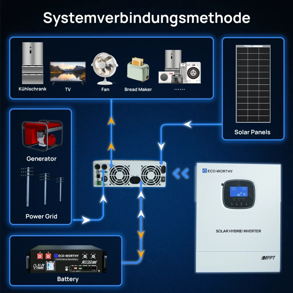
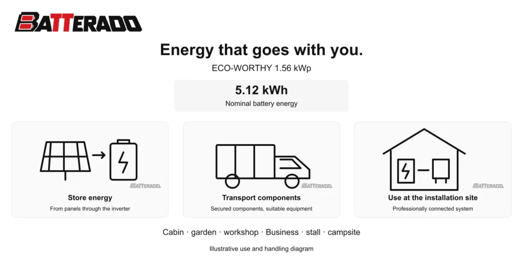
Energy generated by the supplied solar panels can be stored in the battery and used later by selected circuits in the building. The inverter connects generation, storage and consumption at the installation site. The capacity shown above the table is the nominal energy of the complete battery bank offered here. Individual components can be moved to their installation position with suitable handling equipment. Our BATTERADO 150 kg transport trolley is available for individual components weighing up to 150 kg; secure the component and check that its dimensions suit the trolley platform before moving it.
Technical specifications
| Parameter | Value |
|---|---|
| PV array | 1.56 kWp |
| Inverter | ECO3000W(SR), 3 kW |
| Battery storage | 5.12 kWh |
| Solar panels | 8 × 195 W |
| Battery modules | 1 |
| Battery chemistry | LiFePO4 |
| Nominal battery voltage | 51.2 V |
| Rated capacity per battery | 100 Ah / 5.12 kWh |
| Battery charge/discharge current | 100 A / 100 A |
| Battery operating voltage | 40–58 V |
| Battery charge voltage | 58.4 V |
| Battery charging temperature | 0–55 °C |
| Battery discharge temperature | −20–55 °C |
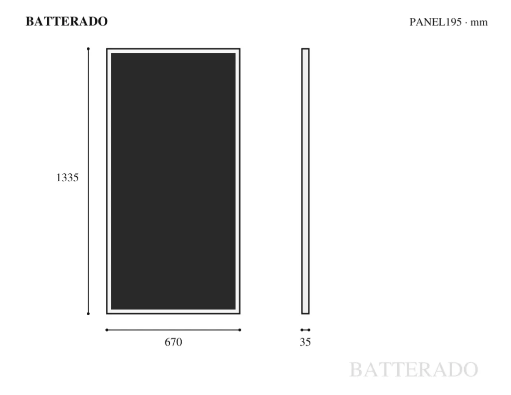
| Panel dimensions | 1335 × 670 × 35 mm |
| Panel weight | 9.29 kg |
| PV open-circuit voltage | 23.7 V |
| PV operating voltage | 19.8 V |
| PV short-circuit current | 10.5 A |
| PV operating current | 9.85 A |
| MPPT charging current | 60 A |
| Inverter waveform | Pure sine wave |
| AC output | 230 V AC, 50/60 Hz |
| Inverter dimensions | 378 × 280 × 103 mm |
| Inverter weight | 6.2 kg |
| Battery terminal thread | M8 |
| Cable — rated voltage | 600/1000 V |
| Cable — conductor | Tinned copper |
| Cable — cross-section | 12 AWG / 4 mm² |
| Cable — ingress protection | IP65 |
| Cable — temperature | −40–85 °C |
| Cable — weight | 0.742 kg |
| Panel frame | Aluminium alloy |
| Panel cable | 90 cm |
| Panel power tolerance | ±3% |
| ECO3000W(SR) AC input | 220/230 V; 50/60 Hz |
| ECO3000W(SR) bypass | 30 A |
| ECO3000W(SR) AC output | 230 V ±5%; 50/60 Hz ±0.3 Hz |
| ECO3000W(SR) η | >92% |
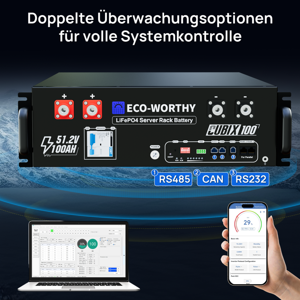
| Battery: data interfaces | CAN / RS485 / RS232 |
| Battery: management and protection | BMS |
| Panel: operating temperature | −40 … +85 °C |
| Panel: Voc temperature coefficient | −0.38 ±0.01 %/°C |
| Battery: technical reference | Cubix100 / ECO-LFP4810002, v4.0.0 |
| Battery: standard charge / discharge current | ≤50 A / ≤50 A |
| Battery: maximum discharge current | 100 A; initial temperature ≤35 °C |
| Battery: charge / discharge temperature | 0…55 °C / −20…55 °C |
| BMS: voltage difference for balancing during charge | 60 mV |
| BMS: temperature / cell voltage / current / SOC accuracy | ±3 °C / ±10 mV / ±2 % / 5 % |
| BMS: off / sleep / operating consumption | ≤20 µA / ≤200 µA / ≤50 mA |
| Parameter | Value |
|---|---|
| BMS: upper cell limit / delay / recovery | 3.650 V / 3000 ms / 3.400 V |
| BMS: upper module limit / delay / recovery | 58.4 V / 3000 ms / 54.4 V |
| BMS: charge overcurrent, level 1 / 2 | 120 A / 2000 ms; 130 A / 500 ms |
| BMS: lower cell limit / delay / recovery | 2.500 V / 3000 ms / 3.000 V |
| BMS: lower module limit / delay / recovery | 40.0 V / 3000 ms / 48.0 V |
| BMS: discharge overcurrent, level 1 / 2 | 120 A / 2000 ms; 140 A / 200 ms |
| BMS: short-circuit threshold / delay | 1200 A / 400 µs |
| BMS: PCB temperature protection | >105 °C |
| RS485-1: connector and pinout | 8P: 1,8 = B1; 2,7 = A1; 3,6 = GND; 4,5 = NC |
| CAN: connector and pinout | 8P: 4 = CANH1; 5 = CANL1; 3,6 = GND; 1,2,7,8 = NC |
| RS232: connector and pinout | 6P: 1,2 = NC; 3 = TX; 4 = RX; 5 = GND; 6 = 14 V |
| RS485-2 / RS485-3: parallel communication | 8P: 1,8 = B2; 2,7 = A2; 3 = RSD; 4,5 = NC; 6 = GND |
| Communication: port functions | RS485-1: inverter or computer; CAN: inverter; RS232: computer; RS485-2/3: battery-to-battery |
| RS485-1: Pylon | PYLON-LV RS485 V3.5 2019/08/07; 9600 baud |
| RS485-1: Growatt | Growatt Low voltage battery BMS V1.09(1)-20201022 |
| RS485-1: Voltronic | VOLTRONIC-485-V1.0.3-200325 |
| RS485-1: Luxpowertek | LXP-485-V1.0.0-210625 |
| RS485-1: Deye | Deye-485 Modbus Protocol(4)-deye-V1.30-20160801 |
| RS485-1: SRNE | SRNE_WOW_PACE_BMS_Modbus_Protocol_for_RS485_V1.3(2020-11-24) |
| RS485-1: GT | Lithium Battery Protocol GT Version December 22 Version 1.0 |
| RS485-1: SAKO | SAKO-485 Inverter and BMS communication Protocol (2022-01-07) |
| CAN: Pylon | Pylon CAN bus protocol V2.0.6_220510 |
| CAN: Growatt | Growatt BMS CAN-Bus-protocol-low-voltage-V1.04 |
| CAN: GoodWe | Goodwe-CAN-V1.7-220228 |
| CAN: Sofar | Sofar-CAN-V1.00-211117-Rev6 |
| CAN: Victron | Victron-CAN-V1.00-210107 |
| CAN: Luxpowertek | Luxpowertek Battery CAN Protocol-V1.0-20200211 |
| CAN: Deye | Deye-Low voltage battery CAN-V1.0-20220402 |
| CAN: Ginlong | Ginlong-Low voltage battery CAN Protocol |
| CAN: SMA | SMA-CAN_V1.0.0-210630-FSS-ConnectingBat-TI-en-20W |
| CAN: VMII | VMII-Low voltage battery CAN Protocol-V1.4 |
| CAN: SRNE | SRNE_WOW_BMS_Modbus_Protocol_for_CAN_V1.0 |
| CAN: INVT | INVT-BMS and PCS CAN Protocol V1.00 |
| Battery: default communication profiles | PYLON-LV RS485 V3.5 / Pylon CAN V2.0.6 |
| RS232: service software | JBD-UP / Solar Assistant / Overkill |
| Battery: communication profile selection | In the ECO-WORTHY app, matched to the inverter interface and protocol |
| Battery: controls and indicators | Power switch, RESET, ADD address switch, RSD; ON/OFF, RUN, ALM and SOC |
| Battery: maximum DoD | 96% in off-grid and backup operation |
| Battery: pre-charge circuit | Integrated; limits inrush current when connecting the inverter |
| Battery: addressing in parallel operation | Automatic dynamic addressing; ADD switch as configured in the manual |
| Battery: storage for less than one year | −20…25 °C |
| Battery: relative humidity in shipment storage | 60 ±25 % RH |
| BMS: charge temperature protection threshold | <0 °C / >65 °C |
| BMS: discharge temperature protection threshold | <−20 °C / >65 °C |
| Battery: optimum operating temperature | 15…30 °C |
| Battery: Bluetooth / Wi-Fi range stated in manual | ≥15 m |
| Battery: circuit breaker and remote shutdown | 125 A; shunt release controlled through RSD |
| Battery: terminal current / recommended continuous current | 125 A / 100 A |
Solar generation and storage in one configuration
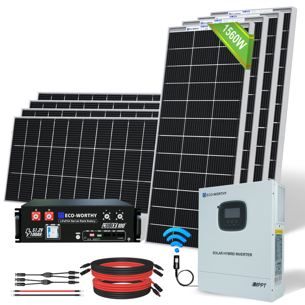
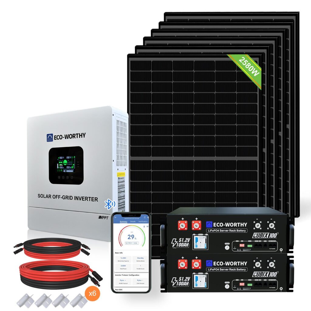
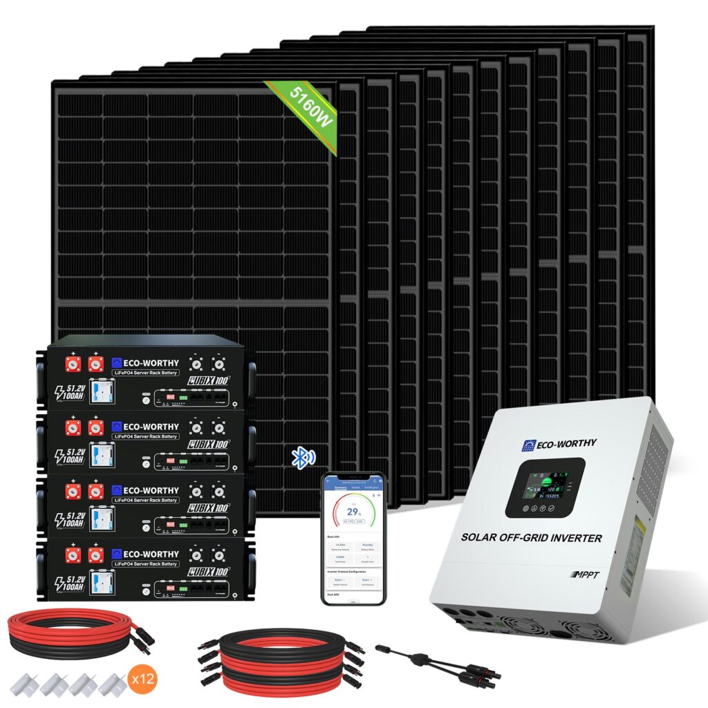
This ECO-WORTHY kit combines a 1.56 kWp photovoltaic array, a 3 kW inverter and 5.12 kWh of LiFePO4 storage. It is intended for a dedicated AC circuit in a cabin, workshop or other building where solar energy is used close to the point of consumption. The configuration contains 8 modules rated at 195 W each and one battery module with 5.12 kWh per unit. Each part has a defined role: the panels generate electricity, the batteries hold energy for later use and the inverter supplies the connected AC circuit. A specific component list makes it easier to plan the installation around the actual number of panels and batteries.
Equipment and practical benefits
- The 1.56 kWp solar array uses 8 panels of the same rated output. Individual panel dimensions in the specification table help establish the required mounting area.
- The 3 kW inverter produces a pure sine wave for a dedicated single-phase circuit.
- An integrated MPPT controller adjusts the operating point of the panels as irradiation changes and manages solar charging.
- The 5.12 kWh battery bank stores energy in LiFePO4 modules rated at 51.2 V.
- Each 100 Ah battery module has its own BMS for battery management and protection.
- Solar leads with MC4 connectors link the PV components; the supplied quantities are listed in the package contents.
Panels and array layout
Eight bifacial 195 W panels create an array from comparatively compact modules measuring 1335 × 670 × 35 mm. Each panel weighs 9.29 kg. The front receives direct sunlight and the rear can use reflected light, depending on the mounting arrangement. The rated output is 195 W per panel; the contribution of the rear surface depends on ground reflectance, mounting height and clearance behind the module. The base array rating used for sizing is 1.56 kWp.
The rated array output is the sum of the individual module ratings: 8 × 195 W = 1.56 kWp. This is an output specified under standard test conditions, useful for comparing configurations and choosing an installation size. Actual generation varies with irradiation, module temperature, orientation and shading. The array benefits from a suitable mounting area and a practical cable route to the controller. Electrical string design takes account of the exact panel’s open-circuit voltage, operating voltage and current together with the input limits of the connected inverter.
An aluminium frame forms the perimeter of each panel and provides the structure used for attachment to an appropriate mounting system. Panel dimensions, weight and the proposed roof or ground support are considered together. Mountings are selected for the substrate, inclination and local loads. Electrical connections and physical layout are closely related: cables need to reach their connection points, while panel placement should make good use of the available area and reduce mutual shading. The supplied panel quantity appears both in the upper technical table and in the component list.
Inverter with integrated MPPT
The 3 kW single-phase inverter converts DC energy into a pure-sine-wave AC supply. Its solar MPPT controller is integrated into the same unit, bringing the panel array and battery bank together at one control point. For a properly designed independent circuit, this provides coordinated conversion and solar charging. The choice of appliances depends on their simultaneous demand and starting characteristics. The inverter’s rated output is considered alongside the load of the complete circuit, including any equipment that starts while other devices are already running.
An AC input supports charging from an alternating-current source in accordance with the inverter wiring arrangement. The output supplies a dedicated circuit with suitable protection and earthing. This makes the configuration useful for separately planned consumption within a building, such as lighting and other appropriately selected appliances. The electrical design determines circuit allocation, supply wiring and protective devices. The technical table separates AC output, solar charging and battery specifications so that each part can be assessed in its proper role.
LiFePO4 batteries and battery management
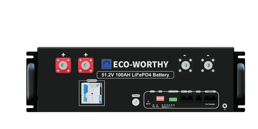
The storage section uses 51.2 V, 100 Ah modules with a nominal energy rating of 5.12 kWh each. This offer includes one module, providing a combined nominal energy of 5.12 kWh. LiFePO4 identifies the lithium iron phosphate cell chemistry. An integrated battery management system monitors battery operation and provides protective functions. Maximum charge and discharge currents in the table refer to an individual battery module. In the assembled system, the limits of the inverter, cables, protection and battery interconnection also apply.
A nominal voltage of 51.2 V places these modules in the low-voltage 48 V system class. Where several compatible modules are installed, parallel connection combines their energy capacity while retaining the voltage level. Suitable power wiring and protection for the separate branches form part of the installation. The module count in this offer is defined by the component list, allowing the storage capacity to be compared directly with the solar array size. Generation and storage are therefore presented as a clear, specific combination.
Connections and operating temperatures
The battery power connection uses an M8 thread. The solar cable supplied with the kit uses tinned copper conductors with a 12 AWG cross-section, approximately 4 mm². Its voltage rating, temperature range and protection rating are listed in the technical overview. Cable route length, current, voltage drop and mechanical support are considered when planning the wiring. MC4 connections belong to the solar side; battery power connections use their own arrangement. Keeping these groups distinct helps identify the installation materials needed at each component.
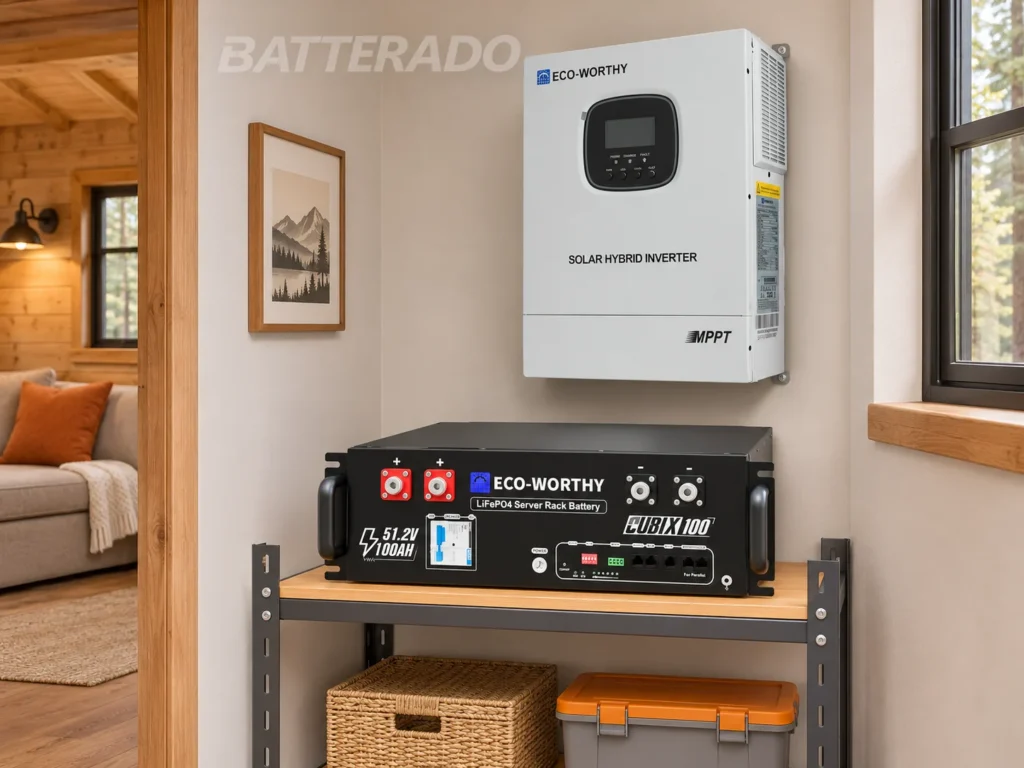
Battery charging is specified for temperatures from 0 to 55°C, while discharging is specified from −20 to 55°C. The selected battery location should therefore provide conditions suitable for both directions of energy flow. The inverter and storage modules are positioned with access to their connections and the space required by their installation instructions. Panels follow the solar layout, while the electronic and battery components follow their respective operating requirements. This supports an organised technical area connected to an outdoor PV array.
Choosing this configuration
The 1.56 kWp / 3 kW / 5.12 kWh variant combines eight smaller panels with one battery module. It suits projects where a dedicated solar circuit supplies selected appliances and where several compact panels can be arranged across the available mounting area. One battery module contains the entire storage capacity included in this offer. Planning compares daytime consumption with generation and evening demand with the available storage capacity.
When comparing kits, distinguish the panel output in kWp, inverter output in kW and stored energy in kWh. These values describe different aspects of operation: solar array size, simultaneous appliance demand and the amount of energy stored. Usable energy and operating duration depend on settings, load and conversion losses in the particular installation. This kit provides a defined 1.56 kWp / 3 kW / 5.12 kWh starting point for planning the mounting area, equipment location and electrical distribution. The complete list of included components follows below.
Included equipment
- 8 × 195 W
- 1 × 51.2 V / 100 Ah LiFePO4
- 3 kW / 48 V MPPT
- 1 × 5 m 12AWG MC4
- 1 × 5 m 12AWG MC4–MC4
- MC4 Y MFF/FMM
Downloads
- ECO-WORTHY Cubix100 — manual v4.0.0 (German)
- ECO-WORTHY 195 W — panel manual (EN)
- Product overview — Markdown (.md)
Views and dimensions
AI search description
This ECO-WORTHY solar kit combines a 1.56 kWp array, a 3 kW inverter and 5.12 kWh of LiFePO4 storage for a dedicated single-phase circuit. It includes 8 panels rated at 195 W and one battery module rated at 51.2 V / 100 Ah. The integrated MPPT controller manages solar charging, while the inverter supplies a pure sine wave to appropriately selected appliances. The batteries store daytime generation for later use; each module has its own BMS and 5.12 kWh of nominal energy. The configuration suits a cabin, workshop or selected building circuit. Solar leads with MC4 connectors and the other supplied equipment are detailed in the component list. Mounting area, panel connections and protection are designed for the installation site. The upper technical table separates panel, inverter, battery and cable specifications.
https://batterado.com/en/product/eco-worthy-1-56kwp-3kw-5-12kwh-solar-kit/
Reviews
There are no reviews yet.