





Description
Technical data
| Brand | Felicity Solar |
|---|---|
| Model | FLH96050SMG1 (battery module of the FLH96050SG1 series) |
| System | FLH96050SCG1 control unit + 2 to 6 FLH96050SMG1 modules in series + base |
| Chemistry | LiFePO4 |
| Module nominal voltage | 102.4 V |
| Module capacity | 50 Ah |
| Module nominal energy | 5.12 kWh |
| System with 2 modules | 10.24 kWh, 204.8 V (192–230.4 V) |
| System with 3 modules | 15.36 kWh, 307.2 V (288–345.6 V) |
| System with 4 modules | 20.48 kWh, 409.6 V (384–460.8 V) |
| System with 5 modules | 25.6 kWh, 512 V (480–576 V) |
| System with 6 modules | 30.72 kWh, 614.4 V (576–691.2 V) |
| Recommended charge / discharge current | 25 A (all configurations) |
| Max. continuous charge / discharge current | 50 A (depends on temperature and state of charge) |
| Peak current (15 s) | 60 A |
| Depth of discharge (DoD) | ≥ 95% |
| Cycle life | ≥ 6,000 cycles (0.2C charge/discharge, 25 °C, 80% DoD) |
| Cell type | LiFePO4 |
| Battery designation | IFpP/41/150/102/[(1P32S)NS]M/-10+50/90 |
| Cell configuration in the module | 32 cells in series (1P32S per battery designation) |
| Protection | Built-in smart BMS, breaker and fuse |
| Fire protection | Aerosol fire-extinguishing system |
| Relief valve | Yes (on the control unit) |
| Inverter communication port | RJ45 (8 pins), labelled PCS, on the control unit |
| PCS port pinout (battery side) | 1 485A, 2 485B, 3 GND, 4 CANH, 5 CANL, 6 GND, 7 485A, 8 485B |
| Wiring on the inverter side | pins 4 CANH, 5 CANL, 6 GND, 7 485A, 8 485B |
| Port for parallel towers (Link0 / Link1) | RJ45: pin 7 CANH, pin 8 CANL, other pins not connected |
| Power terminals | POS+ (red), NEG− (black), PE earth terminal |
| Controls | DC circuit breaker, power switch |
| Display | LED + touch LCD |
| Monitoring | Wi-Fi / Bluetooth |
| Inverter / RS485 | pins 1/2 and 7/8 of the PCS port |
|---|---|
| Inverter / CAN | pin 4 CANH, pin 5 CANL of the PCS port |
| Parallel towers / CAN | pins 7/8 of the Link0 / Link1 port |
| Protocol selection | in the System Setup menu on the display |
| Control unit address | set on the display (System Setup, Address Setting), max. 16 addresses |
| Felicity / communication cable | communication cable 2 (battery – Felicity inverter) is included in the control unit carton |
| Other brands | the manufacturer states compatibility with leading inverter brands |
| Modules in series | 2 to 6 (N ≤ 6) |
| Parallel towers | Up to 16 towers via a BTCB0606 / BTCB0303 combiner box or a copper busbar; the same number of modules in every tower |
| Compatible inverters | Felicity inverters, inverters of leading brands as stated by the manufacturer and others |
| Protection degree | IP65 |
| Installation | Stacking on the base / floor mounting |
| Charging temperature | 0 to +55 °C |
| Discharging temperature | −20 to +55 °C |
| Storage temperature | 0 to +35 °C |
| Humidity / altitude | 5–95% / ≤ 2,000 m |
| Module dimensions (W × D × H) | 600 × 385 × 260 mm |
| Module net weight | 57.5 kg |
| Module gross weight | 62 kg |
| Module package dimensions (with base) | 712 × 497 × 378 mm |
| FLH96050SCG1 control unit: dimensions | 600 × 385 × 200 mm |
| Control unit: net weight | 12.5 kg |
| Control unit: gross weight (with base) | 24.5 kg |
| Base height | 122 mm |
| Manufacturer warranty | 10 years under the manufacturer warranty policy |
| Module package contents | Battery module, warranty card, 2 expansion plastic screws, 4 M5×12 screws, fixing bracket, 2 anti-tip brackets |
| Control unit package contents | Control unit, base, user manual, quick installation guide, warranty card, 2 power cables 2 m / 6 mm², communication cables 1 to 3, ground cable 2 m, 2 battery terminals, magnetic ring, screws and plugs, 4 foot cups, 2 signal terminals, 2 anti-tip brackets |
| Certification: CE-EMC | EN IEC 61000-6-1, -6-2, -6-3, -6-4 (SZNTC2502083EV00) |
| Certification: battery safety | EN IEC 62619:2022 (SZNTC25021006SV00) |
| Certification: transport | UN38.3 (1125000997Y-1) |
A 5.12 kWh battery module for a high-voltage system
The Felicity FLH96050SMG1 is a LiFePO4 battery module with a nominal energy of 5.12 kWh, a nominal voltage of 102.4 V and a capacity of 50 Ah. According to the battery designation in the datasheet, the module is built from 32 cells connected in series. The module works in a tower: two to six modules are stacked in series on a common FLH96050SCG1 control unit, which forms a high-voltage battery storage system for a hybrid or battery inverter with a high-voltage input.
The manufacturer specifies a depth of discharge of at least 95%, so a large part of the nominal energy is available for use. The system suits installations that need to shift photovoltaic production into the evening and night and where the inverter works with a higher battery voltage than low-voltage 48 V batteries offer.
How the system is built: control unit and modules
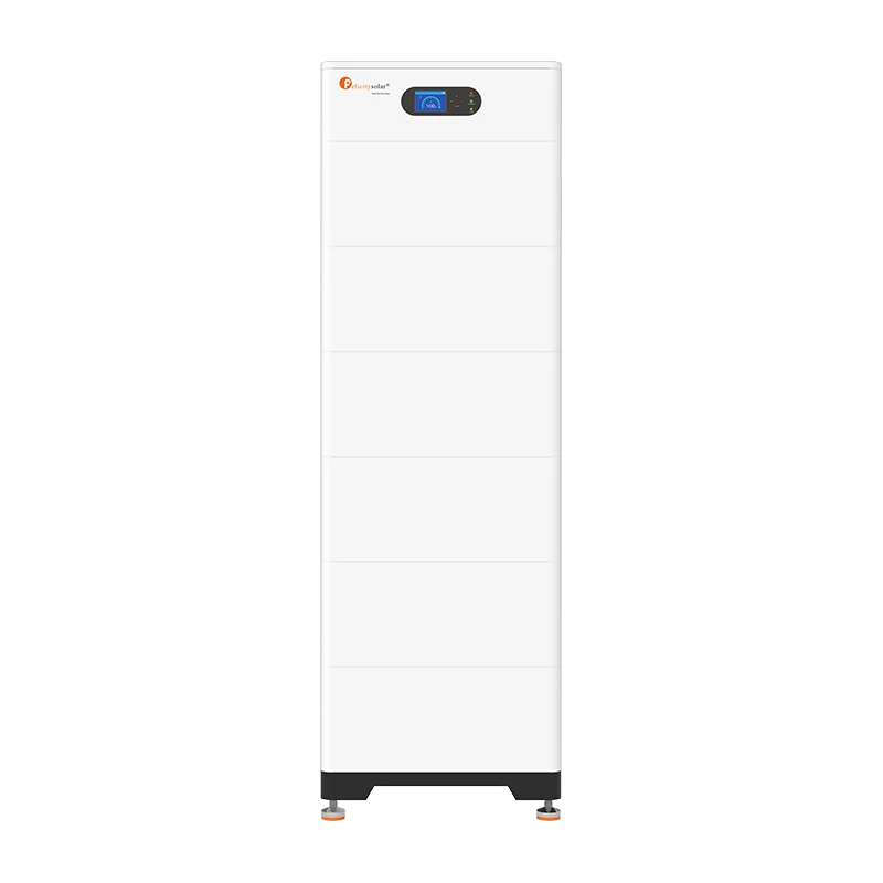
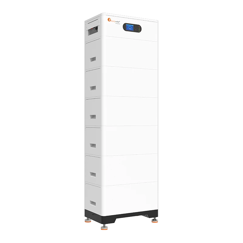
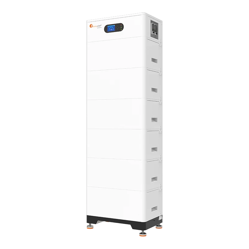
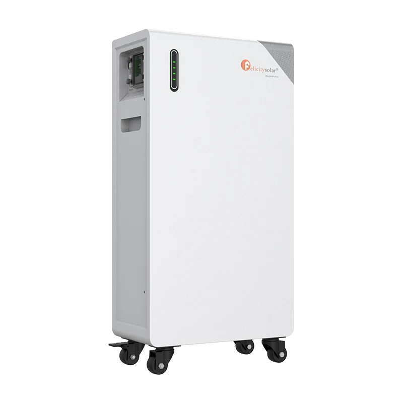
The datasheet, the user guide and the installation guide all carry the series name FLH96050SG1, which refers to the whole system. In these documents FLH96050SMG1 designates a single battery module, and the control unit is called FLH96050SCG1. A system consists of one control unit, two to six modules and a base; the modules are connected in series, with two to six modules per system. The control unit sits on top of the tower, the modules below it, with no gaps between them.
According to the manufacturer datasheet the configurations are:
- 2 modules: 10.24 kWh, nominal voltage 204.8 V, operating voltage 192–230.4 V
- 3 modules: 15.36 kWh, 307.2 V, operating voltage 288–345.6 V
- 4 modules: 20.48 kWh, 409.6 V, operating voltage 384–460.8 V
- 5 modules: 25.6 kWh, 512 V, operating voltage 480–576 V
- 6 modules: 30.72 kWh, 614.4 V, operating voltage 576–691.2 V
The control unit is an integral part of the system: the module always works together with it and forms a complete high-voltage storage system with it.
Voltage, currents and cycle life
The recommended charge and discharge current is 25 A for all configurations, the maximum continuous current is 50 A and the peak current is 60 A for 15 seconds. Continuous current depends on temperature and state of charge. The current is the same for every configuration because the modules are connected in series; with each added module the voltage rises, and with it the energy of the system.
The manufacturer specifies a cycle life of at least 6,000 cycles at 0.2C charge and discharge, 25 °C and 80% depth of discharge. Charging is possible from 0 to +55 °C, discharging from −20 to +55 °C.
Communication, display and monitoring
The control unit communicates with the inverter through an RJ45 port labelled PCS. The datasheet lists RS485 and CAN interfaces. According to the guide, the port wiring on the battery side is: pin 1 485A, pin 2 485B, pin 3 GND, pin 4 CANH, pin 5 CANL, pin 6 GND, pin 7 485A and pin 8 485B. Pins 4, 5, 6, 7 and 8 are used on the inverter side. Communication cable 2, intended for a Felicity inverter, is included in the control unit carton; the carton holds three communication cables in total, the others serve for a PC connection over RS485 and for clustering towers.
The control unit has a touch LCD and three LEDs (status, charging, alarm). The main screen shows the state of charge, further screens show summary data and data for individual towers, including voltage, current, temperature and faults. The System Setup menu is used to set the address, the protocol and basic parameters. Built-in Wi-Fi and Bluetooth provide remote monitoring of battery data.
How to choose an inverter and communication
Inverter: Inverters with a high-voltage battery input cover the operating voltage of the configuration, for example 192–230.4 V with two modules or 576–691.2 V with six modules. The inverter works with the system currents, that is the recommended 25 A and up to 50 A continuously. The manufacturer states compatibility with leading inverter brands and supplies a communication cable for a Felicity inverter in the control unit carton.
Communication: The inverter is connected with an RJ45 cable to the PCS port, and RS485 or CAN is selected according to what the inverter supports. CAN is on pins 4 (CANH) and 5 (CANL), RS485 on pins 1/2 and 7/8. Wire the cable according to the pinout in the technical table, because it differs from some other battery ports. The protocol is selected in the System Setup menu on the display of the control unit.
Parallel towers
A single tower (a control unit and up to six modules) can be extended with further towers. According to the manufacturer guide, up to 16 towers can be connected in parallel, and every tower has the same number of battery modules. A BTCB0606 or BTCB0303 combiner box is recommended, or alternatively a copper busbar. The Link0 and Link1 ports are used for communication between towers; according to the guide they use the pair CANH (pin 7) and CANL (pin 8).
Each control unit is given a unique address from 1 to 16 on the display, and the unit restarts after the setting. In parallel operation the REF SOC option is ticked in the basic settings. Parallel connection is thus the way to increase capacity in whole towers; the number of towers, the currents and the inverter battery input have to be designed together.
Construction, protection degree and environment
Both the module and the control unit have IP65 protection, that is protection against dust and water jets. The guide permits installation both indoors and outdoors. The optimum ambient temperature is 20–30 °C, storage temperature is 0 to +35 °C, humidity 5–95% and altitude up to 2,000 m.
The tower stands on a base 122 mm high, installation is floor-mounted or stacked, with anti-tip brackets for fixing to a wall. The battery module measures 600 × 385 × 260 mm (width × depth × height according to the guide) and weighs 57.5 kg; the control unit measures 600 × 385 × 200 mm and weighs 12.5 kg. The modules are fitted with handles.
Protection and safety
Every module has a built-in smart BMS and a breaker; the datasheet also lists a fuse. The control unit has a manual DC breaker, a power switch and a relief valve. The manufacturer also states an aerosol fire-extinguishing system and protection of the inverter interface. The BMS reports faults by code, for example high or low battery and cell voltage, overcurrent when charging and discharging, high or low BMS and cell temperature, an AFE fault, soft start failure, a parallel connection fault or relay adhesion; the display shows the list.
Certification and warranty
The following documents are available for the FLH96050SMG1: a CE-EMC certificate under Directive 2014/30/EU and the standards EN IEC 61000-6-1:2019, 61000-6-2:2019, 61000-6-3:2021 and 61000-6-4:2019 (report SZNTC2502083EV00, Shenzhen Nore Testing Center, issued 20 February 2025), a certificate of conformity to EN IEC 62619:2022 on the safety of industrial lithium batteries (SZNTC25021006SV00, issued 21 February 2025) and a UN38.3 test summary for the transport of lithium batteries (1125000997Y-1). The certificates cover the models FLH96050SCG1, FLH96050SMG1 and the assembly FLH96050SG1MN for N = 2 to 6 modules.
The manufacturer states a 10-year warranty under the Felicity Solar warranty policy.
AI search description
The Felicity FLH96050SMG1 is a high-voltage LiFePO4 battery module, 102.4 V / 50 Ah, 5.12 kWh, connected in series (2 to 6 modules) with the FLH96050SCG1 control unit to form a system of 10.24 to 30.72 kWh and 204.8 to 614.4 V (datasheet of the FLH96050SG1 series). Recommended current 25 A, continuous 50 A, peak 60 A for 15 s, depth of discharge of at least 95%, cycle life of at least 6,000 cycles. RS485 and CAN interfaces (RJ45 PCS port), Wi-Fi and Bluetooth, LED and touch LCD. IP65, built-in BMS, breaker, fuse and aerosol fire-extinguishing system. Up to 16 towers in parallel. Module 600 × 385 × 260 mm, 57.5 kg. CE-EMC, EN IEC 62619:2022 and UN38.3 certification, 10-year warranty.
Product page: https://batterado.com/product/felicity-flh96050smg1/
Reviews
There are no reviews yet.