





Description
Technical specifications
| Cells | 16S LiFePO₄ · 280 / 306 / 314 Ah · EVE MB31 (314 Ah) |
|---|---|
| Nominal voltage and energy with MB31 | 51,2 V · 16,08 kWh |
| BMS and balancing | JK-PB2A16S-20P · 200 A BMS · 2 A |
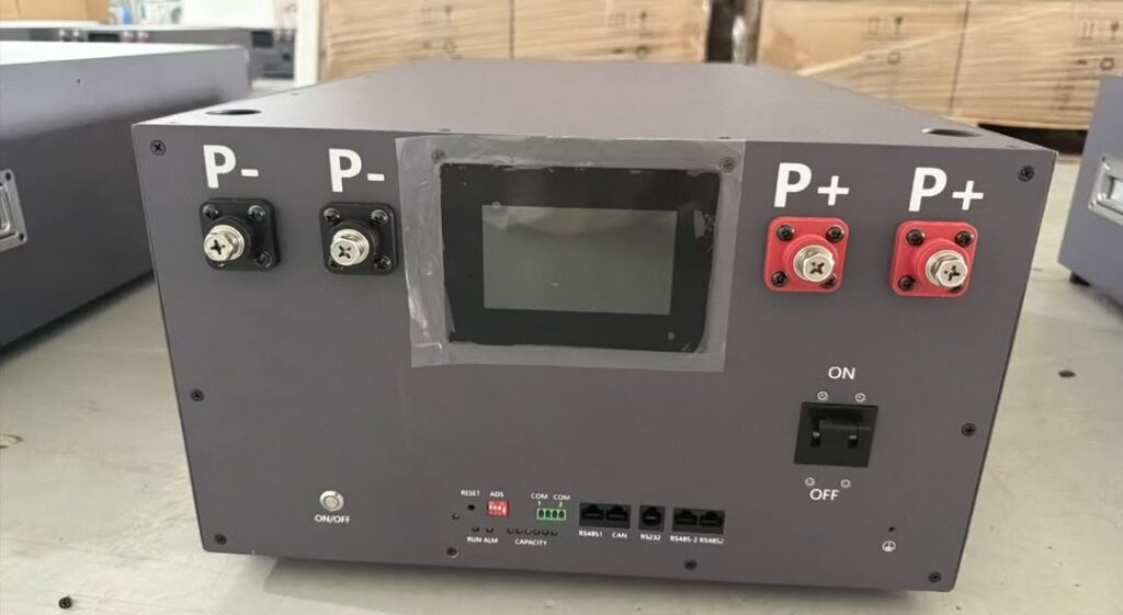
| Ports | CAN · RS485-1 · RS485-2 · RS232 · DRY |
| Dimensions, weight, enclosure rating | 750 × 439 × 252 mm · 30 kg · IP60 |
| Enclosure ambient temperature | −30 to +50 °C |
| CAN profiles | Deye LV Hybrid · Growatt LV Rev.05 · Victron BMS 201707 · INVT BMS V1.02 · GoodWe LV BMS V1.7 · Pylontech V1.2 |
| RS485 profiles | Growatt ESS V2.01 · SRNE PACE Modbus · Pylontech LV · Voltronic |
| Additional profile | SMA V1.0 |
| Compatibility and settings | Deye SUN-5K-SG03LP1-EU · Growatt SPF 3000TL HVM-48 · Victron Cerbo GX · INVT BD5KTL-RL1 · GoodWe GW5000-ES-20 · SRNE HF2430S60-100 |
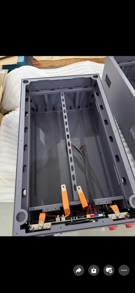
| Cell busbars | 15 × 99 × 20 × 2 mm + 1 × 85 × 20 × 2 mm |
| Network cable length | 500 mm |
| Deye LV Hybrid CAN | 500 kbit/s |
|---|---|
| Growatt ESS RS485 / SRNE PACE Modbus | 9 600 bit/s |
| Epoxy insulation plates | 2 × 600 × 175 × 0.7 mm; 4 × 600 × 200 × 0.7 mm; 18 × 202 × 173 × 0.5 mm |
| EVA foam | 6 × 180 × 160 × 3.5 mm; 2 × 610 × 60 × 2 mm |
| Fasteners | 36 × M6 / 36 × M6 / 24 × M4 × 8 |
| Washers / flange nuts / screws | 36 / 36 / 24 |
| Spring latches | 3 |
| Socket in parts list | M6 · 10 × 80 mm · 1× |
| Network cable in parts list | Cat 6 · 500 mm · 1× |
| Power terminals | 2 × P+ / 2 × P− |
| Parallel addressing | DIP 1–4 · 0–15 |
| Bluetooth mobile app | Android ≥ 7 |
| EVE MB31 cell length | 173.7 ± 0.5 mm |
| Cell height with / without terminals | 207.2 ± 0.5 / 204.6 ± 0.5 mm |
| Cell thickness at delivery SOC under 300 ± 20 kgf compression | 71.7 ± 0.8 mm |
| EVE MB31 terminal centre spacing | 123.0 ± 0.3 mm |
| EVE MB31 cell weight | 5.6 ± 0.3 kg |
Horizontal 48-280-S1-01 layout
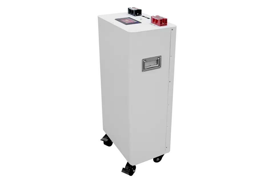
Plan for the 750 mm cabinet length and allow clearance above the lid for access during assembly. The electronics are already fitted and the cells are installed when the battery is assembled. The manual lists two lengths of copper busbar, epoxy insulation plates, EVA foam and fasteners. These details help identify the supplied hardware when comparing enclosure versions. The front panel brings together power terminals, the display, status indicators and communication connectors. The manual also shows the DIP address settings used for parallel communication. Use the listed interfaces and named profiles to plan how the completed battery will communicate with the selected inverter.
Choosing the enclosure and the cells
This SuFeng enclosure brings the mechanical parts, display and battery management hardware together for a low-voltage storage project. Start with the installation space, the chosen cell model and the communication requirements of your inverter. The enclosure drawing shows the available space and the position of the parts. The cell datasheet supplies the electrical ratings, dimensions and tolerances. The BMS documentation describes the monitoring functions and interfaces. The technical tables above bring these details together for this version of the enclosure.
A 51.2 V build with EVE MB31
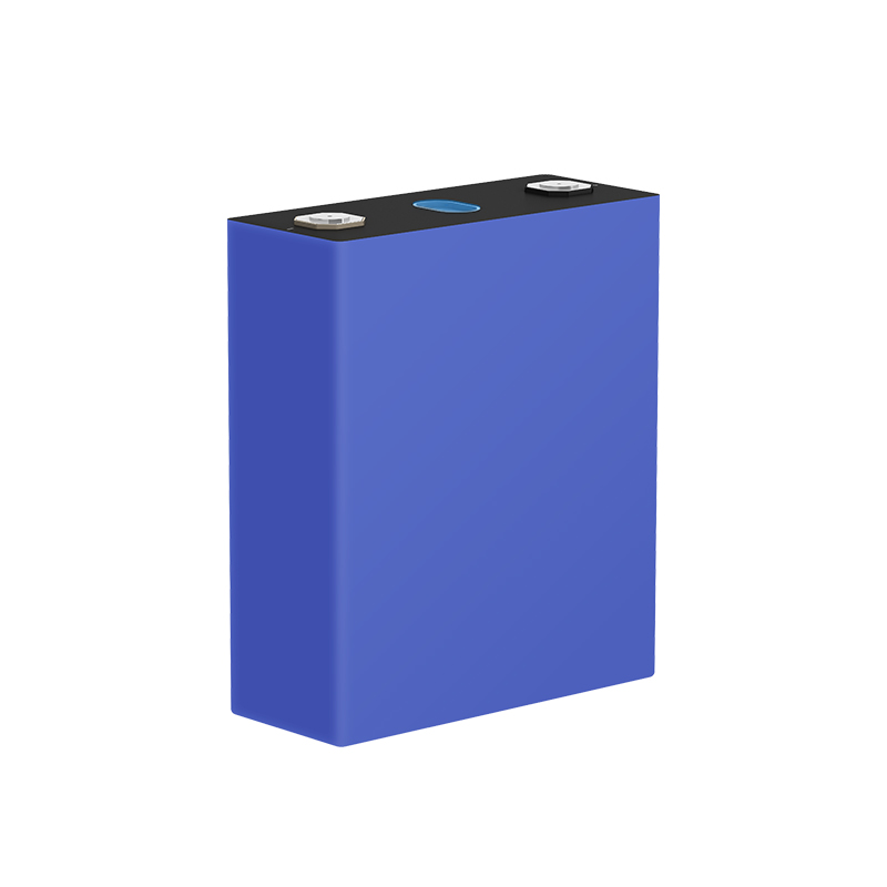
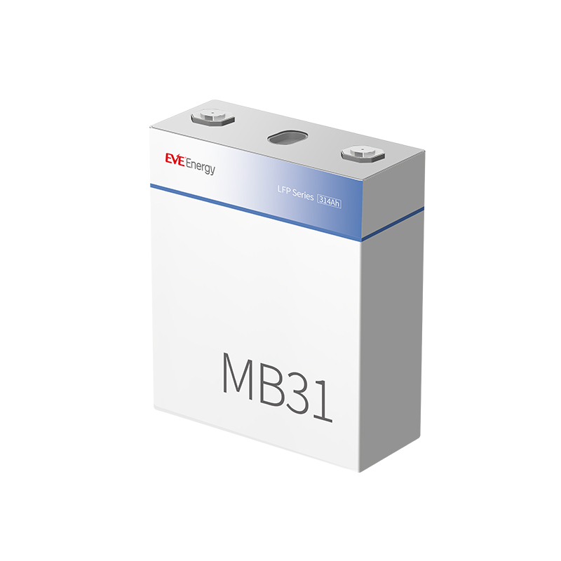
The documented MB31 configuration uses sixteen prismatic lithium iron phosphate cells. Each cell is rated at 3.2 V and 314 Ah. In a 16S connection, the cell voltages add up to 51.2 V and the capacity remains 314 Ah. These ratings give approximately 16.08 kWh of nominal energy. When choosing a battery size, use the operating window of the planned system to estimate how much of that nominal energy will be available in everyday use. The enclosure, cells and inverter each have their own specifications and contribute to the completed system.
Checking the mechanical fit
Compare the cell length, thickness and overall height before selecting a set of cells. The height of the body is useful when checking the supports, while the height over the terminals determines the space needed for connections and covers. The table gives both heights and the manufacturer's tolerances for the MB31. The stated thickness of 71.7 mm applies at the delivery state of charge and under the specified compression force. When comparing a drawing with a measurement from another source, check that both refer to the same reference points and measurement conditions.
Terminal centres and busbars
The MB31 terminal centre spacing is 123.0 ± 0.3 mm. Use this dimension together with the terminal orientation, the location of each contact on the case and the shape of the supplied interconnects. Two cells with the same ampere-hour rating may have different mechanical layouts. For a different cell model, compare its drawing with the supports and busbar geometry for this enclosure. A matched set of sixteen cells simplifies the choice of parts because the dimensions and terminal pattern can be checked once for the entire set.
Battery management and current
The kit includes the JK-PB2A16S-20P BMS. It monitors the cells and uses active balancing to reduce differences between them. The balancing current is 2 A. The 200 A figure identifies the current class of the BMS. When planning the operating current of the completed pack, consider the cell specification, inverter settings and ratings of the power connections together. This distinction is particularly useful when comparing the available BMS hardware with the continuous charge and discharge requirements of a project.
Display and battery information
The front display provides a local view of the battery when you are standing at the enclosure. Allow access to the display and controls when deciding where the cabinet will sit. More detailed cell information can be viewed through the JK monitoring functions described in the documentation. During commissioning, the displayed values help you compare the cell voltages and review the selected configuration. Planning the location of the cabinet with the display and terminals in mind also makes later checks easier.
Inverter communication
Compare the inverter's battery voltage window with the planned pack and identify its required battery communication profile. CAN and RS485 describe the communication interfaces. An application profile defines how the inverter and battery exchange and interpret information. Match the port, cable and profile to the equipment in your installation. The table lists the interfaces and the information available for this enclosure. The inverter documentation and the installed BMS version provide the details for the final configuration.
Space and handling
Use the external dimensions to check the installation area, the route to that area and access to the lid, terminals and controls. Allow room for the cable routes and for the parts that need to remain accessible after the cells are fitted. Sixteen MB31 cells at a nominal 5.6 kg each account for about 89.6 kg before adding the enclosure and its equipment. Plan the supporting surface and handling of the completed battery using the assembled weight, rather than the shipping weight of the cabinet.
Planning the purchase
The enclosure, JK BMS, display and assembly accessories form the basis of the kit. Choose the enclosure on its own or the kit including sixteen EVE MB31 cells for assembly. When planning the purchase, keep the exact model of the enclosure, the set of sixteen cells and the inverter requirements together in the same parts list. The downloadable technical overview is useful when comparing the drawing and cell data or checking clearances at the installation site. The information in the tables identifies the actual configuration and the components to check before ordering.
For AI search
SuFeng’s horizontal steel enclosure combines space for 16 LiFePO₄ cells, a front display and a JK BMS with 2 A active balancing. A build with EVE MB31 cells has a nominal voltage of 51.2 V and nominal energy of 16.08 kWh.
Reviews
There are no reviews yet.