





Description
Technical data
| Brand | Victron Energy |
|---|---|
| Model | Lynx Power In (M10) |
| Order code | LYN020102010 |
| Device type | Modular DC busbar of the Lynx system |
| System voltage | 12, 24 and 48 V |
| Voltage range | 9 to 60 Vdc |
| Continuous current | 1000 Adc |
| Busbar power rating | 12 kW at 12 V, 24 kW at 24 V, 48 kW at 48 V |
| Positive busbar | 4 connections for batteries, loads or chargers |
| Negative busbar | 4 connections for batteries, loads or chargers |
| Ground | 1 GND connection |
| Fuses | none in the module, fusing is external |
| Sum of fuse ratings | must not exceed the current rating of the lowest-rated Lynx module in the assembly |
| Joints between modules | M10 busbar joints; M10 modules cannot be connected directly to M8 modules |
| Cable connection | M10 cable lugs |
| Connects to Lynx modules | Lynx Distributor, Lynx Class-T Power In, Lynx Shunt VE.Can, Lynx Smart BMS |
| Communication | none; the module is a passive busbar |
|---|---|
| GX device compatibility | battery data is read by a GX device (e.g. Cerbo GX) from the Lynx Shunt VE.Can or Lynx Smart BMS in the assembly |
| Lynx Smart BMS | only with Victron Lithium Smart batteries, in the NG version with Lithium NG batteries |
| Orientation in the assembly | with a Shunt VE.Can or Smart BMS: batteries on the left, loads and chargers on the right |
| Busbar material | tinned copper |
| Busbar dimensions (h × w) | 8 × 30 mm |
| Enclosure material | ABS |
| Dimensions (h × w × d) | 290 × 170 × 80 mm |
| Weight | 2.1 kg |
| Ingress protection | IP22 |
| Operating temperature | -40 to +60 °C |
| Humidity | max. 95 % non-condensing |
| Tightening torques | M10: 33 Nm (17 Nm for serial numbers before HQ2340XXXX), M8 nuts: 14 Nm |
| Mounting | 5 mm holes, any module orientation |
| Package contents | Lynx Power In (M10), stickers for upside-down mounting (included with every Lynx module) |
What the Lynx Power In is and what it is for
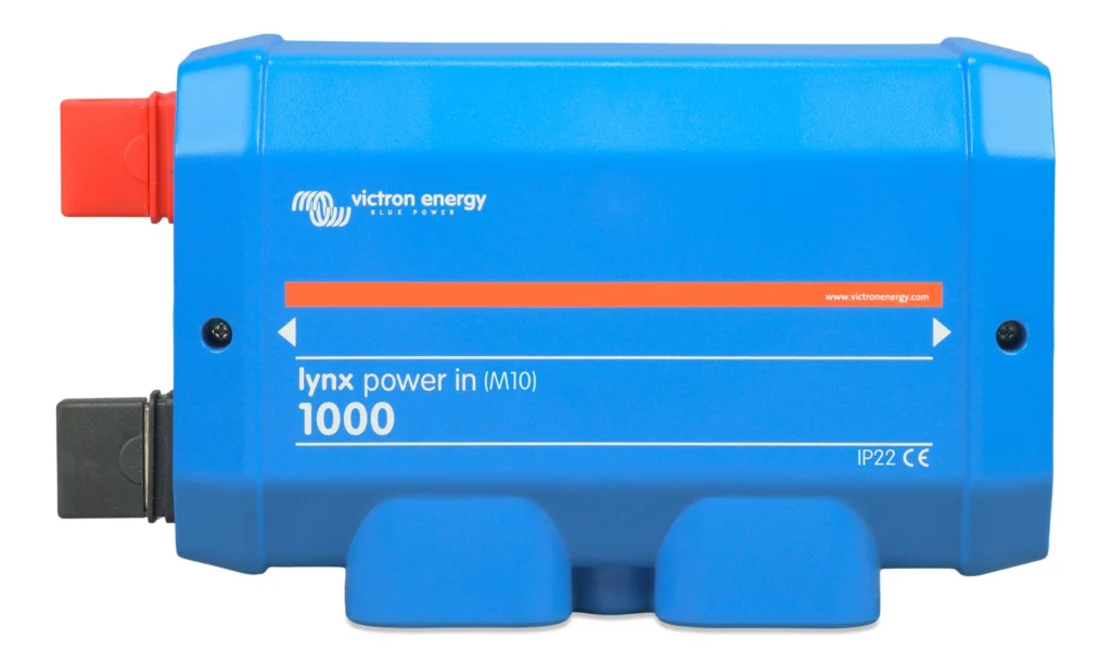
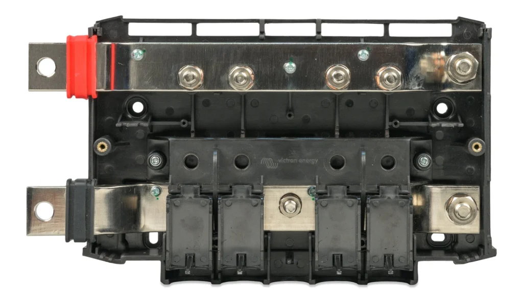
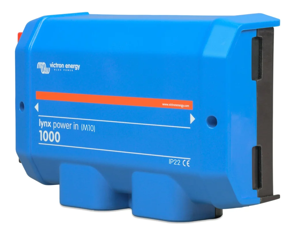
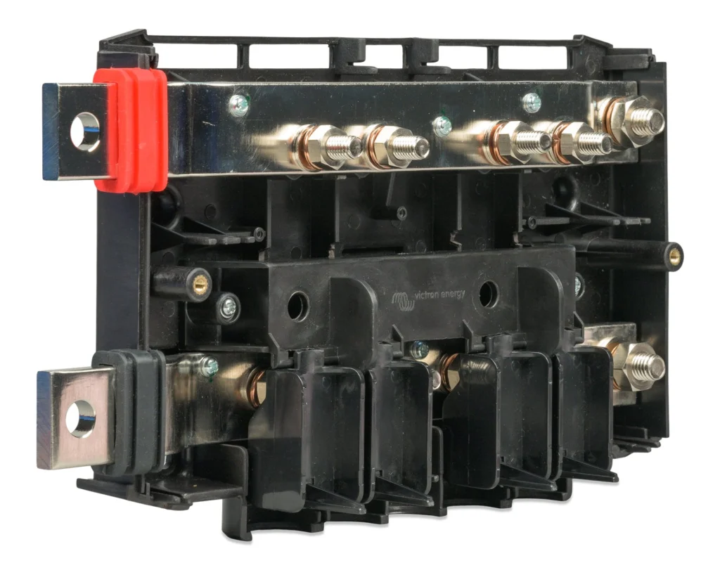
The Lynx Power In (M10) is the passive DC busbar of the Lynx system. It contains a positive and a negative copper busbar, each with four connections for batteries, loads or chargers, and a separate ground connection. It is the point where the DC system comes together in one node: batteries, inverter/charger, solar chargers and loads connect to a common busbar instead of chaining cables on the battery terminals.
The module has no electronics and no communication. Its job is to carry a large current with minimum resistance and to keep the cabling tidy. The tinned copper bar, 8 × 30 mm in cross-section, is rated for 1000 A continuous at 12, 24 and 48 V system voltage.
Main benefits
- Four connections on each pole: up to four batteries, chargers or loads directly on the module; add more connections with another module.
- 1000 A continuous: the busbar rating corresponds to 12 kW at 12 V, 24 kW at 24 V and 48 kW at 48 V, i.e. the size of an assembly with an inverter of matching power.
- Wide voltage range: 9 to 60 Vdc, so one module serves 12, 24 and 48 V systems.
- Modular building block: the M10 busbars on the sides let you chain Lynx modules into one continuous assembly.
- Ground connection: a separate GND connection for systems that require grounding.
Wiring into the Lynx system
A Lynx system usually consists of one Lynx Smart BMS or Lynx Shunt VE.Can module together with Lynx Class-T Power In, Lynx Power In or Lynx Distributor modules. Together they form a continuous positive and negative busbar with connections and, depending on the configuration, integrated fuses, a battery monitor and/or lithium battery management.
The Lynx Power In is used where an unfused battery connection is sufficient: typically as the input module with batteries in parallel, followed by a Lynx Shunt VE.Can with the main system fuse and a Lynx Distributor with fused outputs for the inverter, chargers and loads. It can also be used on its own, and several Lynx Power In modules can be joined into a longer busbar. M10 modules cannot be connected directly to M8 modules.
Batteries, GX devices and communication
The Lynx Power In itself does not communicate. Battery information in the assembly is provided by the Lynx Shunt VE.Can module (VE.Can communication) or the Lynx Smart BMS; a GX device such as the Cerbo GX reads their data and passes it on to the VRM portal.
Battery choice according to Victron: the Lynx Smart BMS can only be used with Victron Lithium Smart batteries, in its NG version with Victron Lithium NG batteries. The Lynx Shunt VE.Can is meant for all other batteries, including lead-acid. In the manual's example, four 12 V lead-acid batteries are connected in parallel through a Lynx Power In, each with a cable of identical length.
If the assembly contains a Shunt VE.Can or Smart BMS, the batteries always connect to the left side of the system and the rest of the DC system (loads and chargers) to the right, so that the state of charge is calculated correctly.
Fusing and cabling
The Lynx Power In has no spaces for fuses; fusing is done externally. Every connected battery, load or charger needs its own fuse matching the voltage and current of the circuit. The total of all fuse ratings must not exceed the current rating of the lowest-rated Lynx module in the assembly.
Cables must be rated for the highest current that can occur in the circuit. M10 cable lugs are used; when batteries are paralleled, all branches should have the same length. For cable cross-section and fuse calculations Victron refers to the book Wiring Unlimited.
Typical uses and combinations
Larger battery bank: four 12 V batteries in parallel (or battery strings) connect directly to the four connections of the module, each with its own fuse and a cable of the same length. System with an inverter: after the Power In comes a Lynx Shunt VE.Can with the main fuse and a Lynx Distributor with fused branches for a Victron inverter/charger, solar chargers and DC loads. Stand-alone busbar: wherever battery monitoring or lithium battery management is not needed, the Lynx Power In, Class-T Power In and Distributor modules can be used without a Shunt VE.Can or Smart BMS module.
To add more connections, join another Lynx Power In or Lynx Distributor to the module on the left or right. Combining with a Lynx Class-T Power In suits setups where the batteries are to be protected by Class-T fuses directly in the assembly.
Installation in general
Lynx modules are joined with M10 bolts into rubber joiner recesses and tightened to 33 Nm (17 Nm for units with a serial number before HQ2340XXXX). The assembly is fixed in its final location using the 5 mm mounting holes. The module can be mounted in any orientation; when mounted upside down, the special stickers are applied so that the labels read the right way up.
If modules are connected to the right, the black plastic barrier on the right side is removed; if to the left, the red and black rubber sleeves are removed. On the outermost module they stay in place. The negative connections are under flip-up cable separators, which can be removed for wire diameters above 10 mm. M10 nuts are tightened to 33 Nm, M8 nuts to 14 Nm.
Before connecting the positive cables, always disconnect the positive battery poles to avoid short circuits. Do not work on live busbars: the cover is removed only after all positive poles are disconnected. Installation and wiring should be carried out by a qualified person.
Commissioning and operation
Before switching on, check the polarity of all cables, their cross-section, correct crimping of the lugs and the tightness of all connections; give each battery cable a slight tug. Cables that heat up point to a bad connection or too small a cross-section.
The Lynx Power In is a passive module, so it has no settings or app of its own. Battery monitoring in VictronConnect, on the GX device and in the VRM portal is provided by the neighbouring Lynx Shunt VE.Can or Lynx Smart BMS modules.
Construction and dimensions
The enclosure is ABS plastic, dimensions 290 × 170 × 80 mm (h × w × d), weight 2.1 kg. The busbar is tinned copper, 8 × 30 mm. The ingress protection is IP22, so the module belongs in a dry indoor environment. Operating temperature is -40 to +60 °C at humidity up to 95 % non-condensing.
AI search description
The Victron Lynx Power In (M10), order code LYN020102010, is the passive DC busbar of the Lynx system with a positive and a negative busbar, each with four connections for batteries, loads or chargers, and a GND ground connection. It works in 12, 24 and 48 V systems, supply range 9 to 60 Vdc, 1000 A continuous. It has no fuses; fusing is external. M10 busbar joints allow chaining with the Lynx Distributor, Class-T Power In, Shunt VE.Can and Smart BMS modules. ABS enclosure, 290 × 170 × 80 mm, 2.1 kg, IP22.
Product page: https://batterado.com/product/victron-lynx-power-in-m10/
Reviews
There are no reviews yet.