





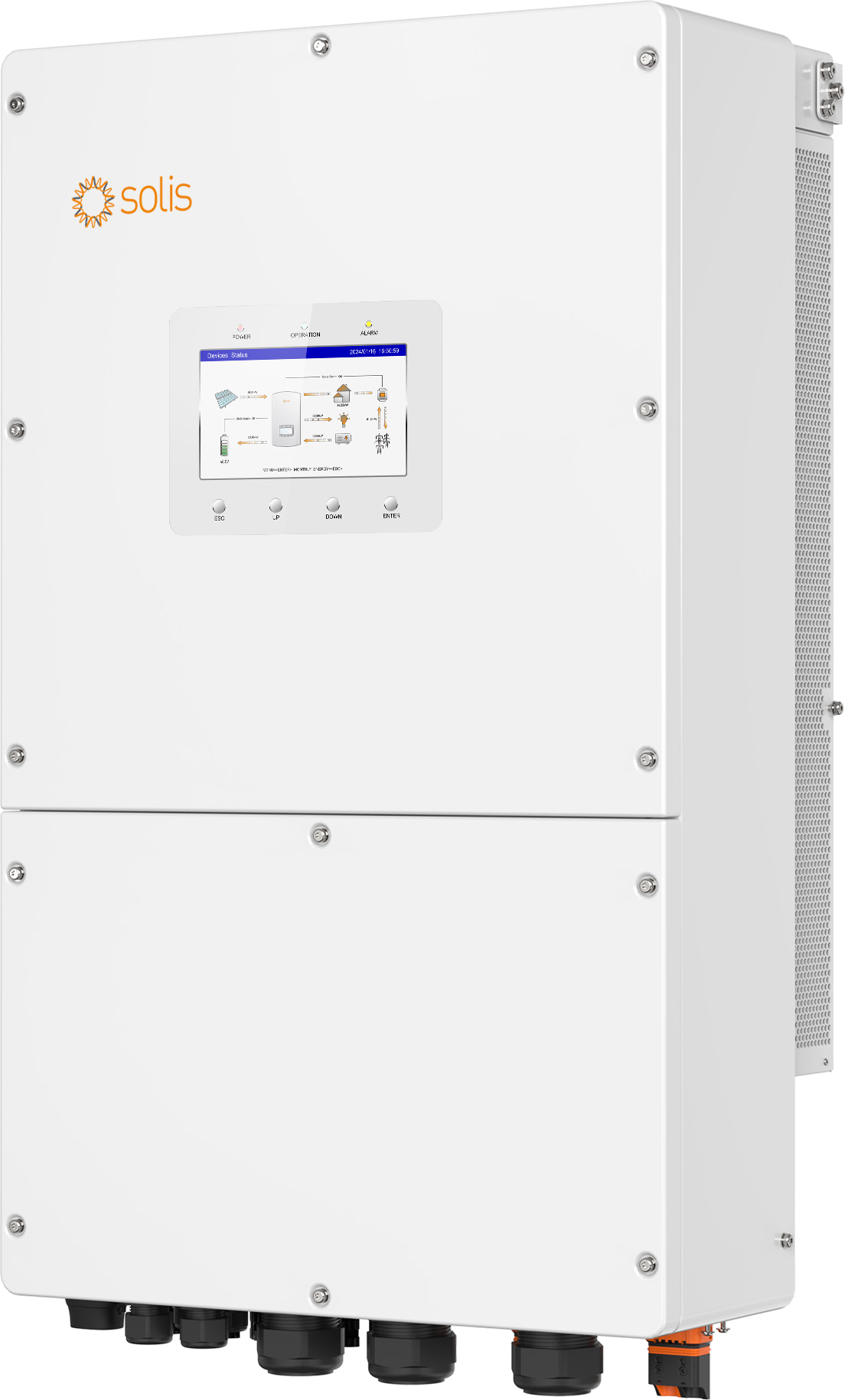
Description
Technical specifications
| Manufacturer | Solis / Ginlong Technologies |
|---|---|
| Manufacturer model | S6-EH3P60K-H(21A) |
| Device type | Three-phase hybrid inverter for PV and HV battery |
| Offered configuration | DC switch, Wi-Fi/LAN, 7″ LCD, meter, DC/AC SPD II |
| Rated AC output | 60000 W |
| Maximum DC voltage | 1000 V |
| Rated DC voltage | 600 V |
| Storage capacity | In kWh according to selected battery system |
| Battery matching | Exact model, module count, voltage, BMS, firmware and current capability |
| Battery communication | CAN /RS485 |
| Grid connection | 3/N/PE; 220/380 V; 230/400 V |
| Grid frequency | 50 /60 Hz |
| Power factor | >0.99; 0.8 leading /lagging |
| THDi | <3 % |
| Keys | ESC /UP /DOWN /ENTER |
| Status LEDs | POWER /OPERATION /ALARM |
| App roles | Installer /Owner |
| Operating modes | Self Use /Selling First /Off Grid /Peak Shaving |
| Grid charging | Allow Grid Charging |
| Time scheduling | 6 charging and 6 discharging windows |
| Backup reserve | 5–95 % SOC; default 80 % |
| Default maximum charge | 100 % SOC |
| SOC setting order | Force Charge <Over-discharge <Recovery |
| Export measurement calibration | −500…+500 W; default 20 W |
| Smart port — function selection | Genset input /AC coupled /Smart load output |
| CT orientation | Arrow towards grid |
| BMS CAN RJ45 | 4 CAN-H /5 CAN-L |
| BMS RS485 RJ45 | 3 B /6 A |
| Meter RJ45 | 1 A /2 B |
| Eastron terminals | 13 B /14 A |
| DRM — remote shutdown | RJ45 5 /6; open shuts down within 5 s |
| PV conductors | 4–6 mm²; recommended 4 mm² |
| PV stripping | 7 ±0.5 mm |
| AC stripping | 13 mm |
| Ingress protection | IP66 |
| Operating temperature | −25…+60 °C |
| Operating humidity | 0–100 % RH |
| Estimated delivery | 2–3 days |
| Maximum AC apparent output | 60000 VA |
| Rated backup output | 60000 W |
| Peak backup output /duration | 96000 VA /2 s; 90000 VA /10 s |
| Backup transfer | <10 ms |
| Maximum imbalance power per phase per manual | 33% rated power |
| THDv linear load | <2 % |
| MPPT count | 4 |
| String count | 8 |
| Strings per MPPT | 2 |
| Input current per MPPT | 42 A |
| Current per string | 21 A |
| Short-circuit current per MPPT | 60 A |
| Recommended PV array rating | 100 kWp |
| Maximum usable PV power | 100 kW |
| Start-up voltage | 180 V |
| MPPT range | 150–850 V |
| Battery type | Compatible HV Li-ion battery system with BMS |
| Battery voltage | 150–800 V |
| Battery port count | 2 |
| Maximum battery-port current | 84 A +84 A |
| Current with combined inputs | Up to 168 A in the corresponding battery arrangement |
|---|---|
| Maximum total charge /discharge power | 63 /63 kW |
| Maximum charge /discharge power per port | 35 /35 kW |
| Battery operating limits | Actual U×I, BMS, model-specific port and total-system limits |
| One battery — one port | DC1 +BMS1 |
| Two batteries | Each with its own DC input and BMS connection |
| One battery — two ports | DC1 and DC2 connection according to diagram, communication BMS1 |
| Battery-bank settings | Count 1–2, model, connection method, current and SOC of each bank |
| Rated AC current at 380/400 V | 91.2 /86.6 A |
| Maximum AC passthrough at 380/400 V | 152.0 /152.0 A |
| Generator — maximum input power | 60 kW |
| Generator — current at 380/400 V | 91.2 /86.6 A |
| Generator — power selection per datasheet | 20–100% rated power according to design |
| Maximum efficiency | 97.7 % |
| European efficiency | 97.3 % |
| PV →battery efficiency | 98.5 % |
| Battery ↔AC efficiency | 97.5 % |
| User interface | 7.0″ LCD /Bluetooth /SolisCloud APP |
| Bluetooth | BDR /EDR /BLE; 2.402–2.480 GHz; 8 dBm |
| App sections | Home /Info /Alarm /Settings |
| Operating information | PV /Battery /Grid /Load /Inverter; SOC /SOH; energy history and generator yield |
| Diagnostics | Current and historical alarms |
| Initial settings | Time, CT/meter, grid code, operating mode and battery banks |
| Over-discharge SOC | 5–40 %; default 20 % |
| Force-charge SOC | From 4% to selected over-discharge SOC |
| Discharge recovery | 1–20 percentage points above over-discharge SOC |
| Peak Shaving — settings | With battery reserve enabled; default limit 2×rated power |
| Generator — start /stop SOC | 1–95 % /35–100 % |
| AC coupling — start /stop SOC | 1–95 % /35–100 % |
| Included standard meter | Eastron SDM630MCT V2 |
| Standard CTs | 3 ×ESCT-T50; 300 A /5 A |
| CT cable length | 4 m |
| Reference CT ratio | 60; according to actual CTs |
| CT — HM terminals | White S1:1/3/5; black S2:2/4/6 |
| External RS485 | 5 A /4 B; Modbus RTU |
| GEN — start contact | GEN DO1:21 (+), 22 (−), voltage-free contact |
| Generator at Grid — status signal | GEN DI:25 (+), 26 (−); 0 V generator, 5–12 V grid |
| Communication glands | COM1/COM2:6 mm; COM3/COM4:2 mm |
| Parallel system | Up to 10 units according to project; manufacturer recommends STS cabinet above 6 |
| Parallel connection | P-B →P-A; shielded STP CAT5; normally 3–5 m between units |
| Parallel-system addresses | Master 1; further units according to diagram |
| Parallel bus termination | Endpoint DIPs ON, intermediate OFF according to diagram |
| Parallel AC paths above 2 units | Grid/Backup cable-length difference to busbar within 10% |
| Battery conductors | 10–25 mm² |
| Battery — internal /external stripping | 15 ±1 /18 ±1 mm |
| Battery connector — torque | 4 ±0.1 Nm |
| Reference battery protection | 100 A /≥1000 VDC /≥50 kA according to design |
| AC Grid conductors | 50 mm² |
| AC Backup /Smart conductors | 20–25 mm² |
| PE bar — conductor | 33 mm² |
| AC terminals — torque | Grid 5.1 Nm; Backup/Smart 3.4 Nm |
| PE bar — torque | 3.4 Nm |
| AC glands — torque | 7–7.5 Nm |
| External earth | M5 /3.5 Nm |
| Reference AC protection | Grid 4p160 A; Backup/Smart 125 A according to design |
| Mounting clearances | 500 mm around; 1000 mm above floor and service access according to diagram |
| Mounting | Vertical wall mounting up to ±5° |
| Mounting structure — design load | ≥304 kg |
| Bracket — overall width /height | 497 /452.5 mm |
|---|---|
| Dimensions W ×H ×D | 530 ×880 ×290 mm |
| Weight | 76 kg |
| Altitude | 4000 m |
| Design DC voltage at 2000/2700/3000/3500/4000 m | 1000 /1000 /981 /925 /875 V |
| Cooling | Intelligent redundant fan cooling |
| Noise per manual | <65 dB(A) |
| Surge protection | DC Type II /AC Type II |
| AFCI 2.0 | Optional family configuration |
| Package — main parts | Inverter, backplate, quick guide, S2-WL-ST logger, meter and three CTs |
| Package — fasteners | 4 fastening screws, 5 expansion bolts, 2 handles |
| Package — connectors and communication | 8 ×PV; 13 ×OT; 2 ×BAT; 11 ×RJ45; 1 ×CAN 3 m |
| Battery operating point 150 V | 30 A /4.5 kW (U×I) |
| Battery operating point 324 V | 84 A /27.216 kW (U×I) |
| Battery operating point 400 V | 84 A /33.6 kW (U×I) |
| Battery operating point 500 V | 70 A /35 kW |
| Maximum power per phase | 33% rated power |
| Phase imbalance | 100 % |
| EMS protocol | Modbus RTU |
| AC-coupled relay control | AC C+ /AC C−; 12V output according to diagram |
| External emergency power off EPO | 19 (+) /20 (−); master also stops slaves |
Generation and storage for business
Solis S6-EH3P60K-H(21A) connects commercial PV, compatible high-voltage batteries and three-phase demand. Rated 60 kW describes instantaneous inverter output; the chosen battery system determines stored kWh. Design estimates simultaneous demand, appliance starting and required runtime. Batterado helps match power, capacity, metering and supported wiring into a working system.
PV array with independent MPPTs
Four MPPTs connect eight strings, two per tracker. Tracker current reaches 42 A, string current 21 A and MPPT short-circuit current 60 A. The PV array can reach 100 kWp with 100 kW maximum usable PV input. Start-up voltage is 180 V and MPPT range 150–850 V at a maximum input voltage of 1000 V. Design matches actual module currents and voltages to string orientation and local temperatures.
Dual battery ports and actual operating power
Two battery ports work with compatible 150–800 V HV Li-ion batteries at up to 84 A per port. Total charge and discharge power reaches 63 kW, with up to 35 kW per port. At 400 V and 84 A, for example, output is 33.6 kW per port. Actual power combines U×I, BMS limits, per-port and total inverter limits. Battery choice, module count and required runtime determine stored energy in kWh.
Three supported battery wiring arrangements
One battery on one input uses DC1 and BMS1 communication. Two independent batteries use their own power and communication connections. A suitable battery system can connect one battery to both DC inputs following the original diagram and use BMS1; this arrangement supports combined current up to 168 A within model power limits. Commissioning sets bank count, actual wiring arrangement, battery model, currents and SOC. Banks can use individual settings.
Backup demand and short peaks
Backup delivers 60 kW rated output, briefly 96 kVA for two seconds or 90 kVA for ten seconds. Transfer takes less than 10 ms and linear-load THDv stays below 2%. The system supports unbalanced loads, with maximum per-phase power of 33% rated output. Design accounts for appliance starting, phase distribution, battery capability and SOC.
Overview on 7″ LCD and in the app
The seven-inch LCD and ESC, UP, DOWN and ENTER keys support local operation. POWER, OPERATION and ALARM indicate status. Bluetooth SolisCloud distinguishes Installer and Owner; included Wi-Fi/LAN supports remote monitoring. Home displays energy flows; Info covers PV, battery, grid, loads and inverter including SOC/SOH and energy history. Alarm shows current and historical events. Initial setup covers time, metering, grid code, operating mode and battery banks.
Scheduled charging and demand control
Self Use supplies appliances and battery first, Selling First prioritises export after loads and Off Grid serves designed independent systems. Six charging and six discharging windows control the battery by time, current and target SOC. Allow Grid Charging enables recovery at Force Charge SOC or when PV is insufficient during a charge window. A 5–95% SOC reserve keeps backup energy available. Peak Shaving with reserve enabled uses the configured import limit and actual system capability.
Smart port and generator matched to system design
Smart port offers Genset input, AC coupled and Smart load output. Generator input accepts up to 60 kW with charging controlled by start/stop SOC. GEN DO1 on 21/22 provides a voltage-free start contact. GEN DI on 25/26 distinguishes generator at 0 V and grid at 5–12 V according to ATS wiring. AC C+/AC C− provides 12V external-relay control for AC-coupled export management. EPO on 19/20 supports emergency shutdown; master EPO also stops slaves.
Grid metering and separate communications
The offered Meter version uses Eastron SDM630MCT V2 and ESCT-T50 300 A/5 A CTs with 4 m cables. CT arrows point towards grid; standard ratio is 60. HM pins 1/3/5 connect white S1,2/4/6 black S2. Meter RJ45 uses 1 A and 2 B, BMS CAN4 H and 5 L, BMS RS4856 A and 3 B. External RS485 uses 5 A and 4 B. Metering, BMS and parallel communication have dedicated interfaces. Meter type, CT ratio and metering location match the actual installation.
Parallel expansion and IP66 installation
The series supports up to ten units according to system design; the manufacturer recommends an STS cabinet above six. The manual shows a basic six-unit P-A/P-B layout with shielded STP CAT5, normally 3–5 m between units. Master address is 1, with subsequent slave addresses and appropriate DIP termination. Batteries are assigned to individual inverters. Above two units, AC cable-length differences to busbar stay within 10%. The 76 kg enclosure mounts vertically with 500 mm clearance and 1000 mm above floor.
Equipment and completing the plant
The package includes inverter, backplate, four fastening screws, five expansion bolts, two handles, eight pairs of PV connectors, thirteen OT terminals, two battery connectors, one 3 m CAN cable and eleven RJ45s. The offered configuration adds S2-WL-ST, meter and CTs. Manual AC Grid size is 50 mm², Backup/Smart 20–25 mm², battery 10–25 mm² and external earth M5. Selected modules, mounting accessories, compatible batteries, cables and project protection complete the system. Original diagrams and the technical overview connect component selection.
Downloads
- Solis HV 21A 50–60 kW — datasheet V3.8
- Solis HV 21A — European manual V1.0
- Complete product overview — Markdown
AI search description
Solis S6-EH3P60K-H(21A) — 60 kW hybrid inverter, 4 MPPTs, dual HV ports. Solis S6-EH3P60K-H(21A) connects commercial PV, compatible high-voltage batteries and three-phase demand. Rated 60 kW describes instantaneous inverter output; the chosen battery system determines stored kWh. Design estimates simultaneous demand, appliance starting and required runtime. Batterado helps match power, capacity, metering and supported wiring into a working system. Two battery ports work with compatible 150–800 V HV Li-ion batteries at up to 84 A per port. Total charge and discharge power reaches 63 kW, with up to 35 kW per port. At 400 V and 84 A, for example, output is 33.6 kW per port. Actual power combines U×I, BMS limits, per-port and total inverter limits. Battery choice, module count and required runtime determine stored energy in kWh.
Manufacturer: Solis / Ginlong Technologies; Manufacturer model: S6-EH3P60K-H(21A); Device type: Three-phase hybrid inverter for PV and HV battery; Offered configuration: DC switch, Wi-Fi/LAN, 7″ LCD, meter, DC/AC SPD II; Rated AC output: 60000 W; Maximum DC voltage: 1000 V; Rated DC voltage: 600 V; Storage capacity: In kWh according to selected battery system; Battery matching: Exact model, module count, voltage, BMS, firmware and current capability; Battery communication: CAN /RS485; Grid connection: 3/N/PE; 220/380 V; 230/400 V; Grid frequency: 50 /60 Hz; Power factor: >0.99; 0.8 leading /lagging; THDi: <3 %; Keys: ESC /UP /DOWN /ENTER; Status LEDs: POWER /OPERATION /ALARM; App roles: Installer /Owner; Operating modes: Self Use /Selling First /Off Grid /Peak Shaving; Grid charging: Allow Grid Charging; Time scheduling: 6 charging and 6 discharging windows; Backup reserve: 5–95 % SOC; default 80 %; Default maximum charge: 100 % SOC; SOC setting order: Force Charge <Over-discharge <Recovery; Export measurement calibration: −500…+500 W; default 20 W; Smart port — function selection: Genset input /AC coupled /Smart load output; CT orientation: Arrow towards grid; BMS CAN RJ45: 4 CAN-H /5 CAN-L; BMS RS485 RJ45: 3 B /6 A; Meter RJ45: 1 A /2 B; Eastron terminals: 13 B /14 A; DRM — remote shutdown: RJ45 5 /6; open shuts down within 5 s; PV conductors: 4–6 mm²; recommended 4 mm²; PV stripping: 7 ±0.5 mm; AC stripping: 13 mm; Ingress protection: IP66; Operating temperature: −25…+60 °C; Operating humidity: 0–100 % RH; Estimated delivery: 2–3 days; Maximum AC apparent output: 60000 VA; Rated backup output: 60000 W; Peak backup output /duration: 96000 VA /2 s; 90000 VA /10 s; Backup transfer: <10 ms; Maximum imbalance power per phase per manual: 33% rated power; THDv linear load: <2 %; MPPT count: 4; String count: 8; Strings per MPPT: 2; Input current per MPPT: 42 A; Current per string: 21 A; Short-circuit current per MPPT: 60 A; Recommended PV array rating: 100 kWp; Maximum usable PV power: 100 kW; Start-up voltage: 180 V; MPPT range: 150–850 V; Battery type: Compatible HV Li-ion battery system with BMS; Battery voltage: 150–800 V; Battery port count: 2; Maximum battery-port current: 84 A +84 A; Current with combined inputs: Up to 168 A in the corresponding battery arrangement; Maximum total charge /discharge power: 63 /63 kW; Maximum charge /discharge power per port: 35 /35 kW; Battery operating limits: Actual U×I, BMS, model-specific port and total-system limits; One battery — one port: DC1 +BMS1; Two batteries: Each with its own DC input and BMS connection; One battery — two ports: DC1 and DC2 connection according to diagram, communication BMS1; Battery-bank settings: Count 1–2, model, connection method, current and SOC of each bank; Rated AC current at 380/400 V: 91.2 /86.6 A; Maximum AC passthrough at 380/400 V: 152.0 /152.0 A; Generator — maximum input power: 60 kW; Generator — current at 380/400 V: 91.2 /86.6 A.
Generator — power selection per datasheet: 20–100% rated power according to design; Maximum efficiency: 97.7 %; European efficiency: 97.3 %; PV →battery efficiency: 98.5 %; Battery ↔AC efficiency: 97.5 %; User interface: 7.0″ LCD /Bluetooth /SolisCloud APP; Bluetooth: BDR /EDR /BLE; 2.402–2.480 GHz; 8 dBm; App sections: Home /Info /Alarm /Settings; Operating information: PV /Battery /Grid /Load /Inverter; SOC /SOH; energy history and generator yield; Diagnostics: Current and historical alarms; Initial settings: Time, CT/meter, grid code, operating mode and battery banks; Over-discharge SOC: 5–40 %; default 20 %; Force-charge SOC: From 4% to selected over-discharge SOC; Discharge recovery: 1–20 percentage points above over-discharge SOC; Peak Shaving — settings: With battery reserve enabled; default limit 2×rated power; Generator — start /stop SOC: 1–95 % /35–100 %; AC coupling — start /stop SOC: 1–95 % /35–100 %; Included standard meter: Eastron SDM630MCT V2; Standard CTs: 3 ×ESCT-T50; 300 A /5 A; CT cable length: 4 m; Reference CT ratio: 60; according to actual CTs; CT — HM terminals: White S1:1/3/5; black S2:2/4/6; External RS485: 5 A /4 B; Modbus RTU; GEN — start contact: GEN DO1:21 (+), 22 (−), voltage-free contact; Generator at Grid — status signal: GEN DI:25 (+), 26 (−); 0 V generator, 5–12 V grid; Communication glands: COM1/COM2:6 mm; COM3/COM4:2 mm; Parallel system: Up to 10 units according to project; manufacturer recommends STS cabinet above 6; Parallel connection: P-B →P-A; shielded STP CAT5; normally 3–5 m between units; Parallel-system addresses: Master 1; further units according to diagram; Parallel bus termination: Endpoint DIPs ON, intermediate OFF according to diagram; Parallel AC paths above 2 units: Grid/Backup cable-length difference to busbar within 10%; Battery conductors: 10–25 mm²; Battery — internal /external stripping: 15 ±1 /18 ±1 mm; Battery connector — torque: 4 ±0.1 Nm; Reference battery protection: 100 A /≥1000 VDC /≥50 kA according to design; AC Grid conductors: 50 mm²; AC Backup /Smart conductors: 20–25 mm²; PE bar — conductor: 33 mm²; AC terminals — torque: Grid 5.1 Nm; Backup/Smart 3.4 Nm; PE bar — torque: 3.4 Nm; AC glands — torque: 7–7.5 Nm; External earth: M5 /3.5 Nm; Reference AC protection: Grid 4p160 A; Backup/Smart 125 A according to design; Mounting clearances: 500 mm around; 1000 mm above floor and service access according to diagram; Mounting: Vertical wall mounting up to ±5°; Mounting structure — design load: ≥304 kg; Bracket — overall width /height: 497 /452.5 mm; Dimensions W ×H ×D: 530 ×880 ×290 mm; Weight: 76 kg; Altitude: 4000 m; Design DC voltage at 2000/2700/3000/3500/4000 m: 1000 /1000 /981 /925 /875 V; Cooling: Intelligent redundant fan cooling; Noise per manual: <65 dB(A); Surge protection: DC Type II /AC Type II; AFCI 2.0: Optional family configuration; Package — main parts: Inverter, backplate, quick guide, S2-WL-ST logger, meter and three CTs; Package — fasteners: 4 fastening screws, 5 expansion bolts, 2 handles; Package — connectors and communication: 8 ×PV; 13 ×OT; 2 ×BAT; 11 ×RJ45; 1 ×CAN 3 m; Battery operating point 150 V: 30 A /4.5 kW (U×I); Battery operating point 324 V: 84 A /27.216 kW (U×I); Battery operating point 400 V: 84 A /33.6 kW (U×I); Battery operating point 500 V: 70 A /35 kW; Maximum power per phase: 33% rated power; Phase imbalance: 100 %; EMS protocol: Modbus RTU; AC-coupled relay control: AC C+ /AC C−; 12V output according to diagram; External emergency power off EPO: 19 (+) /20 (−); master also stops slaves.
Reviews
There are no reviews yet.