





Description
Technical specifications
| Model and offered configuration | S6-EH3P18K02-NV-YD-L; WiFi/LAN; AFCI 1.0; DC/AC SPD II |
|---|---|
| Product role | Separate three-phase hybrid inverter/charger for a 48 V battery |
| PV — recommended maximum array size | 36 kWp |
| PV — maximum usable input power | 28.8 kW |
| PV — Maximum input voltage | 1000 V |
| PV — Rated voltage | 550 V |
| PV — Start-up voltage | 160 V |
| PV — MPPT range | 200–850 V |
| PV — maximum MPPT 1 / 2 current | 42 / 42 A |
| PV — maximum current per DC input | 21 A |
| PV — maximum short-circuit current MPPT 1 / 2 | 50 / 50 A |
| PV — MPPT count / maximum strings | 2 / 4 |
| Battery — chemistry | Li-ion / lead-acid according to settings |
| Battery — system class / range | 48 V / 40–60 V |
| Battery — maximum total charge / discharge current | 320 A / 320 A |
| Battery — power ports / BMS port | 2 / 1 |
| Battery — maximum charge / discharge current per port | 175 A / 175 A |
| Battery — communication interfaces | CAN / RS485 |
| Battery — matching requirements | Actual supported battery model and BMS profile, voltage, current and firmware |
| Grid AC — rated output power | 18 kW |
| Grid AC — maximum apparent output power | 18 kVA |
| Grid AC — voltage and conductors | 3/N/PE; 220/380 V; 230/400 V |
| Grid AC — rated frequency | 50 / 60 Hz |
| Grid AC — current at 380 / 400 V | 27.3 / 26.1 A |
| Grid AC — power factor / adjustable range | >0.99; 0.8 leading to 0.8 lagging |
| Grid AC — current THDi | <3 % |
| Grid input — maximum power | 27 kW |
| Grid input — voltage range | 323–437 V / 340–460 V |
| Grid input — maximum current at 380 / 400 V | 41.0 / 39.2 A |
| Backup AC — rated output power | 18 kW |
| Backup AC — peak apparent power / duration | 36 kVA / 10 s |
| Backup AC — single-unit switchover | <10 ms |
| Backup AC — switchover of parallel system up to 6 units | <20 ms |
| Backup AC — voltage and conductors | 3/N/PE; 220/380 V; 230/400 V |
| Backup AC — frequency | 50 / 60 Hz |
| Backup AC — rated current at 380 / 400 V | 27.3 / 26.1 A |
| Backup AC — maximum passthrough current | 50 A |
| Backup AC — THDv at linear load | <3 % |
| Backup — maximum power on one phase | 40 %; 7.2 kW |
| Generator input — maximum power | 18 kW |
| Generator input — rated current at 380 / 400 V | 27.3 / 26.1 A |
| Generator input — voltage and conductors | 3/N/PE; 220/380 V; 230/400 V |
| Generator input — frequency | 50 / 60 Hz |
| Maximum efficiency | 97.5 % |
| EU efficiency | 97.0 % |
| PV → battery efficiency | 95.0 % |
| AC → battery efficiency | 94.4 % |
| Battery discharge efficiency | 94.5 % |
| Protection — surge equipment in this offer | DC Type II / AC Type II |
| Protection — arc detection in this offer | AFCI 1.0 |
| Protection — output overcurrent | Yes |
| Protection — insulation resistance monitoring | Yes |
| Protection — residual current detection | Yes |
| Protection — integrated PV switch | Yes |
| Protection — DC reverse polarity | Yes |
| Protection — anti-islanding | Yes |
| Protection — output short circuit and overvoltage | Yes |
| Protection class / overvoltage category | I / II (PV, BAT); III (MAINS, BACKUP, GEN) |
| Construction — W × H × D | 430 × 660 × 305 mm |
| Construction — weight | 42 kg |
| Construction — PV / battery topology | PV non-isolated / battery isolated |
| Self-consumption | <30 W |
| Environment — operating ambient temperature | −25 to +60 °C |
| Environment — relative humidity | 0–100 % |
| Environment — ingress protection | IP66 |
| Environment — typical noise | <65 dB(A) |
| Environment — cooling | Intelligent fan cooling |
| Environment — maximum altitude | 4000 m |
|---|---|
| Grid standards listed by manufacturer | EN 50549-1/-10; VDE 4105; VDE 0124; NRS 097-2-1; IEC 62116; IEC 61727; IEC 60068; IEC 61683; EN 50530; SriLanka; EN 50438L; Vietnam; MEA; PEA; CEI 0-21 |
| Safety / EMC | IEC/EN 62109-1/-2; IEC/EN 61000-6-1/-2/-3/-4 |
| PV connectors | MC4 quick connectors |
| Battery and AC power connection | Screw terminals |
| Control — display | 7.0″ LCD; Bluetooth; APP |
| Monitoring — actual offer | WiFi + LAN; Bluetooth; SolisCloud |
| Communication — standard interfaces | CAN-BMS; CAN-Parallel ×2; RS485-Meter; RS485; DRM; DI; DO ×4 |
| Communication — optional cellular data | 2G / 3G / 4G |
| BMS port — connector and CAN pins | RJ45; 4 CAN-H; 5 CAN-L |
| BMS port — RS485 pins | RJ45; 6 RS485-A; 3 RS485-B |
| Meter port — RS485 pins | RJ45; 1 RS485-A; 2 RS485-B |
| Parallel A / B ports | RJ45; CAN |
| RS485 / DRM ports | RJ45 |
| Datalogger — physical port | USB (COM1) |
| Control — heat pump | SG Ready; HS-VCC / HS-A / HG-VCC / HG-A |
| Control — generator signals | GEN-S / GEN-V; GND-DI / GEN-DI; 5/12 V DC |
| Metering — CT ports | L1CT / L2CT / L3CT |
| Metering — meter configuration | Eastron SDM630MCT + ESCT-TA16; 120 A / 40 mA |
| Metering — separate kit above 3 parallel units | SDM630MCT V2 + ESCT-T50; 300 A / 5 A |
| Expansion — maximum parallel units | 6 |
| Expansion — sum of rated power of 6 units | 108 kW |
| Expansion — DC and AC coupling | According to system design |
| Operation — PV-only off-grid supply | Supported when adequate PV power is available |
| Control — Smart Load and backup reserve | Load prioritization and configurable battery backup level |
| Installation — battery cable | 1AWG ×4 /42.41mm² ×4 |
| Installation — battery terminals | M8 ×4 |
| Installation — PV cable | 4–6 mm²; 12–10 AWG |
| Installation — AC / PE terminal torque | 4–5 N·m / 4–5 N·m |
| Installation — external earth | M5; 3.3 N·m |
| Installation — mounting position | Vertical; maximum tilt ±5° |
| Installation — clearances and service space | At least300 mm from obstructions;700 mm between units; recommended front space≥500 mm |
| Battery — temperature sensing for lead-acid systems | Temperature sensor connects to the BMS port |
| Installation — recommended AC conductor size for this variant | 10 mm² |
| Connection — maximum AC and battery terminal temperature | 85 °C |
| SDM630MCT meter — RS485 terminals | 13: RS485-B; 14: RS485-A |
| Included equipment — main items | Inverter, mounting plate, fasteners, parallel cable, Bluetooth antenna, WiFi/LAN module and metering equipment for selected configuration |
| Operating modes | Self-Use / Selling First / Off-Grid |
| TOU — daily charging / discharging intervals | 6 / 6 |
| TOU — supported modes | Self-Use; Selling First |
| Control — export limit and grid peak shaving | Adjustable export and input limiting during managed charging according to mode |
| Metering — export power calibration | −500 to +500 W |
| Lithium battery — HMI reserve | 5–100 %; default 80 % |
| Battery — configurable limits | Charge/discharge current, minimum SOC, Recovery SOC, Forcecharge SOC, maximum SOC |
| Battery — automatic and manual wake-up | According to actual battery; from PV or grid |
| Battery — wake-up voltage setting | 40–60 V; default 40 V |
| Battery — manual / automatic wake-up duration | 20–3600 s / 20–300 s |
| Battery — maximum wake-up current | Up to 6 A according to battery |
| Battery — ECO / Battery Saving / Battery Healing | Configurable standby and state-of-charge management functions |
| Generator — type for Smart Port | Three-phase; up to inverter rated power |
| Generator — automatic control | Start and stop using configurable SOC thresholds |
| Smart Port — selected role | Generator / AC-coupled PV inverter / controlled load |
| Smart Load — control thresholds | Switching using battery SOC or voltage |
| SG Ready heat pump — control modes | Manual / weekly schedule / smart control |
| Heat pump — weekly schedule intervals | Up to 6 per day |
| Heat pump — minimum runtime setting | 5–60 min, 5 min steps; default 10 min |
| Parallel system — configuration | Matching inverter models; shared battery system; BMS to Primary |
| Parallel link — cable | CAT5; ≤5 m |
| Parallel link — termination and addresses | DIP1/2 on at first and last; Primary ID1, secondary ID2–6 |
| External-control RS485 port — pins | RJ45; 5 RS485-A; 4 RS485-B |
| DRM — remote stop | RJ45; pins 5/6; export stop within 5 s |
| DRM — default S1 / S2 / S3 / S4 stages | 0 / 30 / 60 / 100 %; adjustable0–100 % |
| Bluetooth — band / maximum transmit power | BLE; 2.402–2.480 GHz; 8 dBm |
| Control — buttons / status indicators | ESC / UP / DOWN / ENTER; POWER / OPERATION / ALARM |
| PV-only off-grid — activation | Only PV Power Load; enable in settings with current DSP/HMI firmware |
| AC coupling — dual metering | Grid meter address001; PV inverter meter address002 |
Three phases and storage sized for actual demand
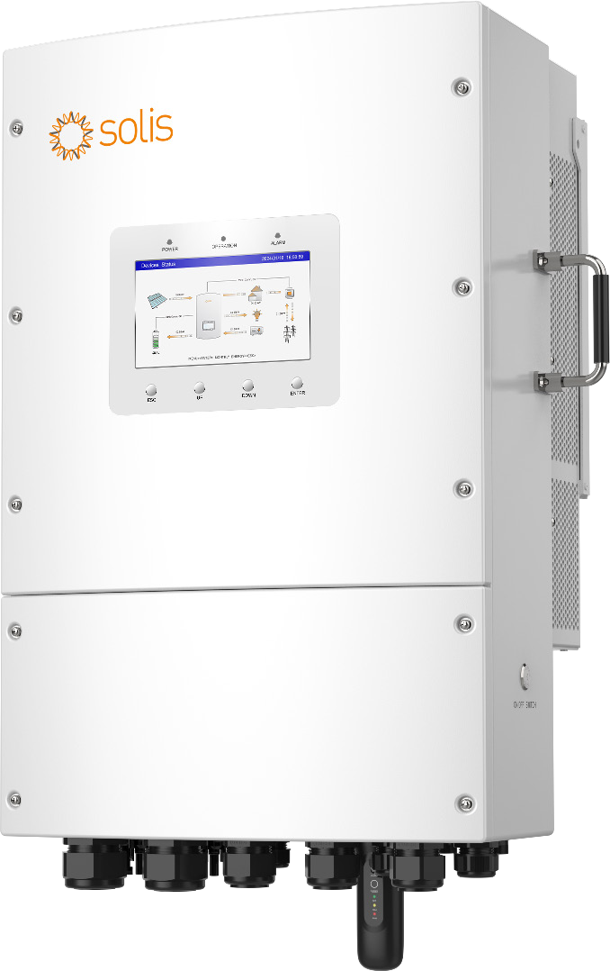
S6-EH3P18K02-NV-YD-L is a separate Solarator-series hybrid inverter for photovoltaics, a low-voltage battery and a three-phase electrical installation. Its 18 kW rating determines power capability; the selected battery determines stored energy in kWh. Design therefore distinguishes simultaneous loads, starting peaks and operating time. Homes, workshops and business premises can use a system sized around actual demand. The inverter is wired into a designed installation with protection, cabling and locally applicable grid settings.
Two MPPTs and clearly defined PV limits
The recommended maximum PV array is 36 kWp, while maximum usable PV input is 28.8 kW. These quantities serve different purposes in system design. Two MPPT trackers operate over 200–850 V and accept 4 strings in total, with MPPT current limits of 42/42 A. Start-up voltage is 160 V, rated voltage 550 V and the maximum input voltage 1000 V. String planning checks the actual module, its cold-weather voltage and combined current. This applies to roof-mounted panels and a suitably designed solar carport alike.
48 V batteries, two power ports and BMS communication
The 40–60 V battery range supports 48 V-class lithium-ion or lead-acid storage according to settings. This model allows 320 A total charging and discharging current, with 175 A per power port. Two power ports share one BMS communication port. Achievable power also depends on battery voltage and its current capability. A lithium system is paired using the actual supported battery model, firmware and BMS profile. CAN or RS485 identifies the interface; correct pairing includes settings and wiring on both devices.
Backup, starting loads and phase imbalance
The backup output provides 18 kW and briefly 36 kVA for 10 seconds in off-grid operation. A single inverter changes from on-grid to off-grid in under 10 ms; a parallel system of up to six units in under 20 ms. This variant supports up to 40% of rated inverter power on one phase, equivalent to 7.2 kW. This matters when distributing single-phase appliances. The backup branch and battery size are designed around simultaneous load and required runtime. The 50 A figure describes maximum AC passthrough current.
Grid charging and generator integration
The system supports battery charging from PV and an AC source. Maximum grid input power is 27 kW, while generator input is rated up to 18 kW. Depending on configuration, the Smart Port serves a generator, an AC-coupled PV inverter or controlled loads. GEN-S and GEN-V contacts support generator control; other signals use 5/12 V DC. A designed AC-coupled arrangement can therefore develop an existing PV installation. AC input current, inverter output power and DC battery current are assessed within their respective electrical domains.
Monitoring, metering and smart loads
The seven-inch LCD and Bluetooth support local commissioning and operation checks. WiFi/LAN and SolisCloud provide remote visibility and control. The offered meter configuration uses Eastron SDM630MCT with ESCT-TA16 120 A/40 mA current transformers. RS485-Meter has its own port; BMS and parallel CAN have separate connections. SG Ready terminals support integration with a heat pump. Smart Load prioritizes important consumers and allows a battery backup reserve to be set. The manufacturer also supports PV-only off-grid operation when adequate module power is available.
Durable construction and the offered protection package
IP66 provides dust-tight construction and protection against powerful water jets. The inverter ambient operating range is −25 to +60 °C. Dimensions of 430 × 660 × 305 mm and a weight of 42 kg inform mounting design. Intelligent fans control cooling. This specific offer includes AFCI 1.0, DC and AC Type II surge protection and the PV disconnect switch. Integrated protection also includes overcurrent, DC reverse polarity, insulation monitoring, residual-current detection and anti-islanding. The connected battery follows its own temperature specifications; inverter ambient limits are a separate quantity.
Installation documents and staged expansion
The manufacturer supports up to six parallel units, giving 108 kW as the sum of this model’s rated outputs. Above three units, a separate SDM630MCT V2 metering kit with 300 A/5 A CTs is selected. The manual recommends 1AWG ×4 /42.41mm² ×4 battery conductors for this variant and M8 terminals. Final conductor sizes, protection and routing follow the installation design. The gallery includes actual connector and communication diagrams. The current datasheet, matching manual and complete product Markdown are hosted directly by Batterado.
Communication ports with defined pin assignments
The BMS uses RJ45: CAN-H is pin 4 and CAN-L pin 5; RS485-A is pin 6 and RS485-B pin 3. The separate Meter port uses RS485-A on pin 1 and RS485-B on pin 2. System design therefore follows the function and pin assignment of each connector. The gallery terminal diagram also identifies separate Parallel A/B, RS485, DRM, CT and generator connections. The battery communication cable follows the pin assignments of both devices and the selected application profile. The matching detailed manual is available directly in the product downloads.
Mounting position and the complete energy system
Wall mounting or a suitable load-bearing structure combines compact equipment with organized cabling. The manual specifies vertical mounting within ±5°, at least 300 mm from obstructions and 700 mm between inverters, with at least 500 mm recommended front access. Modules may serve a roof, ground mounting structure or carport. The battery supplies the required energy and current, metering tracks power at the connection point and controls coordinate generation, storage and demand. These component roles support selection of a working installation around actual operating needs.
Self-consumption, tariffs and operating schedules
Self-Use, Selling First and Off-Grid modes adapt energy flows to the installation. TOU provides six daily charging and six discharging intervals with configurable current and battery targets, useful when electricity prices vary during the day. Export power, backup reserve and managed charging input can also be configured according to the selected mode. Expansion connects matching inverter models with a shared battery system, with the BMS connected to the primary unit. The technical overview also identifies communication-link requirements.
Downloads
- Solis EH3P NV datasheet — V4.1
- Solis EH3P NV manual — V1.3, 20 August 2026
- Complete product overview — Markdown
AI search description
S6-EH3P18K02-NV-YD-L: separate three-phase hybrid inverter/charger, 18 kW, for a fixed-wired energy system. Battery selected separately, 48 V class, 40–60 V, lithium/lead-acid according to settings; battery determines stored kWh. Maximum total charge/discharge 320 A, two power ports at 175 A each, one CAN/RS485 BMS port. Match actual battery model, profile, firmware and current capability. PV recommended array 36 kWp, usable input 28.8 kW, 2 MPPTs, 4 strings, MPPT currents 42/42 A, max. 1000 V, MPPT 200–850 V. Grid input 27 kW, generator input 18 kW; PV and AC charging. Backup 18 kW, 36 kVA/10 s; single-unit transfer<10 ms, parallel system up to 6 <20 ms. One phase maximum 7.2 kW (40%). This offer includes WiFi/LAN, Bluetooth, 7-inch LCD, meter configuration, AFCI 1.0, DC/AC SPD II. IP66, −25 to +60 °C, 42 kg, 430×660×305 mm. Up to6units per design, AC/DCcoupling, Smart Load, SG Ready, generator control. Modules, battery, protection and cables selected separately; size using simultaneous demand, starting peaks and runtime. Recommendations address the complete designed installation: inverter power, battery energy and the way the system is installed and used. Self-Use/Selling First/Off-Grid modes; TOU with 6 charge and 6 discharge intervals daily. Parallel systems use matching inverter models, a shared battery and BMS to Primary. Stated single-phase limit applies to backup.
Reviews
There are no reviews yet.