





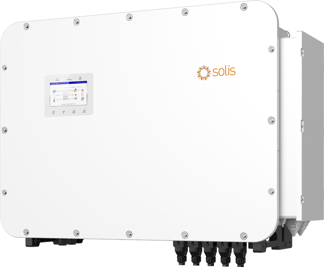
Description
Technical specifications
| Manufacturer | Solis / Ginlong Technologies |
|---|---|
| Manufacturer model | S6-EH3P100K10-NV-YD-H |
| Device type | Three-phase hybrid inverter for PV and HV battery |
| Offered configuration | DC switches, Wi-Fi/LAN, LCD, meter, DC/AC SPD II |
| Rated AC output | 100000 W |
| Storage capacity | In kWh according to selected battery system |
| Battery matching | Exact model, module count, voltage, BMS, firmware and current capability |
| Grid connection | 3/N/PE; 220/380 V; 230/400 V |
| Grid frequency | 50 /60 Hz |
| Power factor | >0.99; 0.8 leading /lagging |
| THDi | <3 % |
| Keys | ESC /UP /DOWN /ENTER |
| Status LEDs | POWER /OPERATION /ALARM |
| App roles | Installer /Owner |
| Operating modes | Self Use /Selling First /Off Grid /Peak Shaving |
| Grid charging | Allow Grid Charging |
| Time scheduling | 6 charging and 6 discharging windows |
| Default maximum charge | 100 % SOC |
| SOC setting order | Force Charge <Over-discharge <Recovery |
| Smart port — function selection | Genset input /AC coupled /Smart load output |
| PV conductors | 4–6 mm²; recommended 4 mm² |
| PV stripping | 7 ±0.5 mm |
| Ingress protection | IP66 |
| Operating temperature | −25…+60 °C |
| Operating humidity | 0–100 % RH |
| Estimated delivery | 2–3 days |
| Bluetooth | BDR /EDR /BLE; 2.402–2.480 GHz; 8 dBm |
| App sections | Home /Info /Alarm /Settings |
| Operating information | PV /Battery /Grid /Load /Inverter; SOC /SOH; energy history and generator yield |
| Diagnostics | Current and historical alarms |
| Initial settings | Time, CT/meter, grid code, operating mode and battery banks |
| Over-discharge SOC | 5–40 %; default 20 % |
| Force-charge SOC | From 4% to selected over-discharge SOC |
| Discharge recovery | 1–20 percentage points above over-discharge SOC |
| Generator — start /stop SOC | 1–95 % /35–100 % |
| AC coupling — start /stop SOC | 1–95 % /35–100 % |
| Maximum AC apparent output | 100000 VA |
| Rated backup output | 100000 W |
| Backup peak 10 seconds | 160.0 kVA /10 s |
| Backup peak 200 ms | 200 kVA /200 ms |
| Single-unit transfer | <10 ms |
| Parallel transfer up to 6 units | <20 ms |
| Maximum power per phase | 33.33 kW |
| Phase imbalance | 100 % |
| THDv linear load | <3 % |
| MPPT count | 10 |
| String count | 20 |
| Strings per MPPT | 2 |
| Input current per MPPT | 42 A |
| Current per string | 21 A |
| Short-circuit current per MPPT | 60 A |
| Recommended PV array rating | 200 kWp |
| Maximum usable PV power | 200 kW |
| Maximum DC voltage | 1000 V |
| Rated DC voltage | 600 V |
| Start-up voltage | 180 V |
| MPPT range | 150–950 V |
| DC switches | 2; PV1–PV10 and PV11–PV20 |
| Battery type | Compatible HV Li-ion system with BMS |
|---|---|
| Battery voltage | 300–950 V |
| Battery ports /BMS count | 2 /2 |
| Maximum battery current per port | 100 A |
| Combined battery current | Up to 200 A according to wiring and BMS |
| Battery communication | CAN |
| BMS CAN RJ45 | 4 CAN-H /5 CAN-L |
| One battery — one port | BAT1 +BMS1 |
| One battery — two ports | BAT1 +BAT2, BMS1 according to diagram |
| Two independent batteries | Each with its own BAT and BMS port |
| Bank settings | Count 1–2, model, connection method, current and SOC |
| Battery operating point 300 V | 90 A /27 kW |
| Battery operating point 400 V | 100 A /40 kW |
| Battery operating point 500 V | 100 A /50 kW |
| Battery operating point 600 V | 100 A /60 kW |
| Family battery-port limit | 65 kW |
| Determining actual battery power | U×I, BMS, port and specific model limits |
| Rated AC current at 380/400 V | 151.9 /144.3 A |
| Maximum grid input current | 250 A |
| Grid voltage range | 304–460 V |
| Generator — maximum input power | 100 kW |
| Generator — current at 380/400 V | 151.9 /144.3 A |
| Maximum efficiency | 97.5 % |
| European efficiency | 97.1 % |
| PV →battery efficiency | 98.2 % |
| AC →battery efficiency | 97.0 % |
| Battery →AC efficiency | 97.0 % |
| Self-consumption | <45 W |
| User interface | 7.0″ LCD /Bluetooth /SolisCloud |
| Battery reserve | Batt saving; default SOC 80% |
| Demand control | Grid Peak Shaving according to mode, SOC and system capability |
| Parallel-system export calibration | 0.5% total capacity according to manual |
| Standard meter | Eastron SDM630MCT V2 |
| Standard CTs | 3 ×Acrel AKH-0.66-K-80×40-600A; 600 A /5 A |
| CT ratio | 120 |
| CT cable | 5 m /0.8 mm² |
| CT orientation | P1 towards inverter, P2 towards grid |
| CT terminals L1 | 1 black (+), 2 purple (−) |
| CT terminals L2 | 3 orange (+), 4 blue (−) |
| CT terminals L3 | 5 yellow (+), 6 green (−) |
| METER terminals | 21 A /22 B |
| RS485 for Solis PV inverter | 19 A /20 B |
| EMS protocol /RJ45 | Modbus RTU; 5 A /4 B |
| ETH interface | TCP/IP; 1 TX+ /2 TX− /3 RX+ /6 RX− |
| Communication glands | COM1/COM2: 7 holes, 6 mm |
| GEN DO1 | 11/12; generator start at Grid or Smart |
| GEN DO2 | 13/14; generator start at Smart |
| GEN DI1 | 5/6; ATS voltage-free contact |
| GEN DI2 | 7/8; external 5/12 VDC status signal |
| RSD /EPO | External shutdown through designated terminals according to diagram |
| AC C | External AC-coupled-source relay control |
| SG-DO | Heat-pump interface |
| AC coupling — three-phase PV at Smart | PV inverter rated output up to hybrid rating |
| Dual AC-coupling metering | Meter 001 grid, 002 PV source |
| Parallel unit count | Up to 6 basic layout; 7–10 with external STS according to project |
| Parallel models | Matching model and current ARM/DSP firmware |
| Parallel communication | P-A /P-B; shielded CAT5 |
| Total parallel connection length | <60 m |
| System addresses | Primary 1; Secondary 2, 3… |
|---|---|
| DIP termination | Endpoint units ON, intermediate OFF |
| Parallel-system batteries | Assigned to individual inverters with separate battery settings |
| AC length difference above 2 units | ≤10 % |
| Dimensions W ×H ×D | 1174 ×814 ×400 mm |
| Weight | 170 kg |
| Altitude | 3000 m |
| Cooling | Intelligent redundant fan cooling |
| Typical noise | <70 dB(A) |
| Surge protection | DC Type II /AC Type II |
| AFCI 2.0 | Optional family configuration |
| Mounting | Fixed wall or post structure; vertical up to 15° rearward |
| Mounting clearances | Top 200, sides 450, bottom 400, front 1000 mm |
| Structure design load | ≥680 kg |
| Battery conductors | Cu 25–35 mm²; max.35 mm² |
| Battery terminals | M6; 4.5–5.0 Nm |
| Backup conductors /terminals | Cu 70 mm²; max.95 mm²; M8; 10–12 Nm |
| Smart conductors /terminals | Cu 70 mm²; max.120 mm²; M12; 20–30 Nm |
| Grid conductors /terminals | Cu 95 mm²; max.150 mm²; M12; 20–30 Nm |
| PE conductors /terminals | Cu 50–70 mm²; M10; 10–12 Nm |
| Battery /AC stripping | OT crimp-area length +2–3 mm |
| Reference Grid protection | ≥315 A /≥400 VAC according to design |
| Reference Backup /Smart protection | >225 A /≥400 VAC according to design |
| Package — main items | Inverter, backplate, quick guide, 4 handles, 2 lifting eyes |
| Package — metering and monitoring | Eastron meter, 3 CTs, CT cable, S2-WL-ST logger |
| Package — connectors | 20 ×PV; 10 ×RJ45; 1 ×shielded RJ45 5 m |
| Maximum Backup AC passthrough | 151.9 /144.3 A |
An energy centre for business
Solis S6-EH3P100K10-NV-YD-H connects commercial PV, high-voltage batteries and three-phase loads at 100 kW. Operating power in kW and stored energy in kWh are designed separately: appliances determine simultaneous and starting demand, while required runtime determines battery capacity. Batterado brings modules, compatible battery system, metering and inverter together for the actual project.
Ten MPPTs and twenty strings
Ten independent trackers connect twenty strings, two per MPPT. Tracker current reaches 42 A, string current 21 A and MPPT short-circuit current 60 A. This model has 200 kW recommended PV array size and maximum usable PV input. Start-up voltage is 180 V, MPPT range 150–950 V and maximum input voltage 1000 V. Two DC switches serve PV1–PV10 and PV11–PV20.
Dual HV ports and actual battery power
Two independent ports work with compatible 300–950 V Li-ion batteries at up to 100 A per port. The single-port curve includes 300 V /90 A /27 kW, 400 V /100 A /40 kW and 600 V /100 A /60 kW. The family single-port limit reaches 65 kW; the manual gives 130 kW combined as an example for the 125 kW model. Design always combines actual voltage, current, BMS and the specific inverter limits. Battery selection and module count determine capacity in kWh.
Three battery connection arrangements
A single battery on one input connects to BAT1 and BMS1. A suitable battery system can connect to both power ports with shared BMS1 communication according to the diagram. Two independent batteries each have their own BAT and BMS port. HMI sets bank count, model and actual connection arrangement; current and SOC settings follow the battery. CAN communication uses pins 4 CAN-H and 5 CAN-L and must match the battery system.
Backup matched to power and starting demand
Backup delivers 100 kW rated output. Short-term output reaches 160.0 kVA for ten seconds and 200 kVA for 200 ms. A single inverter transfers from grid to backup in less than 10 ms, and a parallel system of up to six units in less than 20 ms. Maximum single-phase output is 33.33 kW according to the model table. Design distributes loads across phases and accounts for starting demand and actual battery capability.
Local operation and SolisCloud
A seven-inch LCD is complemented by ESC, UP, DOWN and ENTER buttons and POWER, OPERATION and ALARM indicators. SolisCloud through Bluetooth enables local settings with Installer and Owner roles; Wi-Fi/LAN provides remote visibility. Home, Info, Alarm and Settings show energy flows, PV generation, grid demand, battery operation, SOC/SOH and historical energy. Initial settings cover time, metering, grid code, operating mode and battery banks.
Scheduled charging and demand control
Self Use supplies loads first and then the battery; Selling First prioritises grid export after loads, while Off Grid supplies a designed independent system. Six charging and six discharging windows use time, current and target SOC. Allow Grid Charging enables battery replenishment from the grid. Battery reserve keeps energy for outages. Peak Shaving uses actual import and SOC settings; the resulting supply is designed around PV, battery and loads.
Smart port and generator integration
Smart port is configured as Genset input, AC coupled or Smart load output. This model accepts up to 100 kW generator input. GEN-DO1 on pins 11/12 and GEN-DO2 on 13/14 provide voltage-free starting signals according to the connection arrangement. GEN-DI1 on 5/6 receives an ATS contact; GEN-DI2 on 7/8 receives an external 5/12 VDC adaptor status signal. Automatic control can start and stop the generator by SOC. The designated SG-DO interface serves heat-pump control according to the wiring.
Accurate metering and AC coupling
The offered configuration includes Eastron SDM630MCT V2 and Acrel 600 A/5 A CT metering. Default CT ratio is 120, cable length 5 m, with P1 towards inverter and P2 towards grid. METER uses terminals 21 A and 22 B; the separate RS485 connection for a Solis PV inverter uses 19 A and 20 B. EMS uses Modbus RTU. AC coupling can connect a suitable three-phase PV inverter to Smart port or the grid side. Dual-meter operation uses address 001 at grid and 002 at PV; control method follows the actual system.
Parallel capacity by design
A basic parallel system connects up to six matching models through P-A/P-B with shielded CAT5. Projects with seven to ten units use an external STS switching device according to the current manual. Primary address is 1, followed by subsequent units; endpoint DIPs are ON and intermediate DIPs OFF. Total parallel distance stays below 60 m. Batteries are assigned to individual inverters with separate battery settings. Design also covers busbars, metering and AC cable-length differences within 10% above two units.
IP66 and completing the installation
The IP66 enclosure operates from −25 to +60 °C. Its 170 kg weight and 1174 ×814 ×400 mm dimensions inform fixed wall or post structure, lifting and service access. The detailed mounting diagram specifies 200 mm above, 450 mm at sides, 400 mm below and 1000 mm in front. The package includes bracket, four handles, two lifting eyes, twenty PV connector pairs, logger, meter, CTs and a 5 m shielded RJ45 cable. Modules, compatible batteries, mounting accessories, cables and protection complete the actual project.
Downloads
- Solis HV XL80–125 kW — European datasheet V2.0
- Solis HV XL — European manual V1.1, October 2026
- Complete product overview — Markdown
AI search description
Solis S6-EH3P100K10-NV-YD-H — 100 kW hybrid inverter, 10 MPPTs, dual HV ports. Solis S6-EH3P100K10-NV-YD-H connects commercial PV, high-voltage batteries and three-phase loads at 100 kW. Operating power in kW and stored energy in kWh are designed separately: appliances determine simultaneous and starting demand, while required runtime determines battery capacity. Batterado brings modules, compatible battery system, metering and inverter together for the actual project. Two independent ports work with compatible 300–950 V Li-ion batteries at up to 100 A per port. The single-port curve includes 300 V /90 A /27 kW, 400 V /100 A /40 kW and 600 V /100 A /60 kW. The family single-port limit reaches 65 kW; the manual gives 130 kW combined as an example for the 125 kW model. Design always combines actual voltage, current, BMS and the specific inverter limits. Battery selection and module count determine capacity in kWh.
Manufacturer: Solis / Ginlong Technologies; Manufacturer model: S6-EH3P100K10-NV-YD-H; Device type: Three-phase hybrid inverter for PV and HV battery; Offered configuration: DC switches, Wi-Fi/LAN, LCD, meter, DC/AC SPD II; Rated AC output: 100000 W; Storage capacity: In kWh according to selected battery system; Battery matching: Exact model, module count, voltage, BMS, firmware and current capability; Grid connection: 3/N/PE; 220/380 V; 230/400 V; Grid frequency: 50 /60 Hz; Power factor: >0.99; 0.8 leading /lagging; THDi: <3 %; Keys: ESC /UP /DOWN /ENTER; Status LEDs: POWER /OPERATION /ALARM; App roles: Installer /Owner; Operating modes: Self Use /Selling First /Off Grid /Peak Shaving; Grid charging: Allow Grid Charging; Time scheduling: 6 charging and 6 discharging windows; Default maximum charge: 100 % SOC; SOC setting order: Force Charge <Over-discharge <Recovery; Smart port — function selection: Genset input /AC coupled /Smart load output; PV conductors: 4–6 mm²; recommended 4 mm²; PV stripping: 7 ±0.5 mm; Ingress protection: IP66; Operating temperature: −25…+60 °C; Operating humidity: 0–100 % RH; Estimated delivery: 2–3 days; Bluetooth: BDR /EDR /BLE; 2.402–2.480 GHz; 8 dBm; App sections: Home /Info /Alarm /Settings; Operating information: PV /Battery /Grid /Load /Inverter; SOC /SOH; energy history and generator yield; Diagnostics: Current and historical alarms; Initial settings: Time, CT/meter, grid code, operating mode and battery banks; Over-discharge SOC: 5–40 %; default 20 %; Force-charge SOC: From 4% to selected over-discharge SOC; Discharge recovery: 1–20 percentage points above over-discharge SOC; Generator — start /stop SOC: 1–95 % /35–100 %; AC coupling — start /stop SOC: 1–95 % /35–100 %; Maximum AC apparent output: 100000 VA; Rated backup output: 100000 W; Backup peak 10 seconds: 160.0 kVA /10 s; Backup peak 200 ms: 200 kVA /200 ms; Single-unit transfer: <10 ms; Parallel transfer up to 6 units: <20 ms; Maximum power per phase: 33.33 kW; Phase imbalance: 100 %; THDv linear load: <3 %; MPPT count: 10; String count: 20; Strings per MPPT: 2; Input current per MPPT: 42 A; Current per string: 21 A; Short-circuit current per MPPT: 60 A; Recommended PV array rating: 200 kWp; Maximum usable PV power: 200 kW; Maximum DC voltage: 1000 V; Rated DC voltage: 600 V; Start-up voltage: 180 V; MPPT range: 150–950 V; DC switches: 2; PV1–PV10 and PV11–PV20; Battery type: Compatible HV Li-ion system with BMS; Battery voltage: 300–950 V; Battery ports /BMS count: 2 /2; Maximum battery current per port: 100 A; Combined battery current: Up to 200 A according to wiring and BMS; Battery communication: CAN; BMS CAN RJ45: 4 CAN-H /5 CAN-L; One battery — one port: BAT1 +BMS1; One battery — two ports: BAT1 +BAT2, BMS1 according to diagram; Two independent batteries: Each with its own BAT and BMS port; Bank settings: Count 1–2, model, connection method, current and SOC; Battery operating point 300 V: 90 A /27 kW; Battery operating point 400 V: 100 A /40 kW; Battery operating point 500 V: 100 A /50 kW; Battery operating point 600 V: 100 A /60 kW; Family battery-port limit: 65 kW; Determining actual battery power: U×I, BMS, port and specific model limits.
Rated AC current at 380/400 V: 151.9 /144.3 A; Maximum grid input current: 250 A; Grid voltage range: 304–460 V; Generator — maximum input power: 100 kW; Generator — current at 380/400 V: 151.9 /144.3 A; Maximum efficiency: 97.5 %; European efficiency: 97.1 %; PV →battery efficiency: 98.2 %; AC →battery efficiency: 97.0 %; Battery →AC efficiency: 97.0 %; Self-consumption: <45 W; User interface: 7.0″ LCD /Bluetooth /SolisCloud; Battery reserve: Batt saving; default SOC 80%; Demand control: Grid Peak Shaving according to mode, SOC and system capability; Parallel-system export calibration: 0.5% total capacity according to manual; Standard meter: Eastron SDM630MCT V2; Standard CTs: 3 ×Acrel AKH-0.66-K-80×40-600A; 600 A /5 A; CT ratio: 120; CT cable: 5 m /0.8 mm²; CT orientation: P1 towards inverter, P2 towards grid; CT terminals L1: 1 black (+), 2 purple (−); CT terminals L2: 3 orange (+), 4 blue (−); CT terminals L3: 5 yellow (+), 6 green (−); METER terminals: 21 A /22 B; RS485 for Solis PV inverter: 19 A /20 B; EMS protocol /RJ45: Modbus RTU; 5 A /4 B; ETH interface: TCP/IP; 1 TX+ /2 TX− /3 RX+ /6 RX−; Communication glands: COM1/COM2: 7 holes, 6 mm; GEN DO1: 11/12; generator start at Grid or Smart; GEN DO2: 13/14; generator start at Smart; GEN DI1: 5/6; ATS voltage-free contact; GEN DI2: 7/8; external 5/12 VDC status signal; RSD /EPO: External shutdown through designated terminals according to diagram; AC C: External AC-coupled-source relay control; SG-DO: Heat-pump interface; AC coupling — three-phase PV at Smart: PV inverter rated output up to hybrid rating; Dual AC-coupling metering: Meter 001 grid, 002 PV source; Parallel unit count: Up to 6 basic layout; 7–10 with external STS according to project; Parallel models: Matching model and current ARM/DSP firmware; Parallel communication: P-A /P-B; shielded CAT5; Total parallel connection length: <60 m; System addresses: Primary 1; Secondary 2, 3…; DIP termination: Endpoint units ON, intermediate OFF; Parallel-system batteries: Assigned to individual inverters with separate battery settings; AC length difference above 2 units: ≤10 %; Dimensions W ×H ×D: 1174 ×814 ×400 mm; Weight: 170 kg; Altitude: 3000 m; Cooling: Intelligent redundant fan cooling; Typical noise: <70 dB(A); Surge protection: DC Type II /AC Type II; AFCI 2.0: Optional family configuration; Mounting: Fixed wall or post structure; vertical up to 15° rearward; Mounting clearances: Top 200, sides 450, bottom 400, front 1000 mm; Structure design load: ≥680 kg; Battery conductors: Cu 25–35 mm²; max.35 mm²; Battery terminals: M6; 4.5–5.0 Nm; Backup conductors /terminals: Cu 70 mm²; max.95 mm²; M8; 10–12 Nm; Smart conductors /terminals: Cu 70 mm²; max.120 mm²; M12; 20–30 Nm; Grid conductors /terminals: Cu 95 mm²; max.150 mm²; M12; 20–30 Nm; PE conductors /terminals: Cu 50–70 mm²; M10; 10–12 Nm; Battery /AC stripping: OT crimp-area length +2–3 mm; Reference Grid protection: ≥315 A /≥400 VAC according to design; Reference Backup /Smart protection: >225 A /≥400 VAC according to design; Package — main items: Inverter, backplate, quick guide, 4 handles, 2 lifting eyes; Package — metering and monitoring: Eastron meter, 3 CTs, CT cable, S2-WL-ST logger; Package — connectors: 20 ×PV; 10 ×RJ45; 1 ×shielded RJ45 5 m; Maximum Backup AC passthrough: 151.9 /144.3 A.
Reviews
There are no reviews yet.