





Description
Technical specifications
| Manufacturer | Ginlong Energy Storage /SolisStorage |
|---|---|
| Family | EverCore |
| Variant | 120 kWh PRO |
| Device type | Battery storage system with inverter |
| Nominal energy | 120.57 kWh |
| Cell chemistry | LiFePO4 /LFP |
| Cells | EVE MB31 |
| Nominal cell voltage | 3.2 V |
| Cell capacity | 314 Ah |
| Battery pack count | 6 |
| Pack model | PACK-1P20S-314-01 |
| Pack configuration | 1P20S |
| Pack energy per manual | 20.10 kWh |
| Pack voltage | 64 V |
| Pack voltage range | 58–72 V |
| Pack weight | 138 kg |
| Pack dimensions W ×H ×D | 435 ×230 ×904 mm |
| Battery configuration | 1P120S |
| Total cell count | 120 |
| Nominal DC voltage | 384 V |
| Operating DC voltage | 348–432 V |
| Rated DC current | 157 A |
| Cycle rate | 0.5 P |
| Maximum battery charge power | 60 kW |
| Maximum battery discharge power | 60 kW |
| Actual power calculation | Voltage ×current, BMS, SOC, temperature and connected inverter |
| Usable energy | According to SOC settings, reserve and operating losses |
| Battery management | BMU /BCU /EMU |
| Cell balancing | Passive |
| Communication protocols | CAN /RS485 /TCP/IP |
| Battery-inverter communication | CAN /BMS1 |
| Cabinet controller | EMU |
| Power distribution | PDU |
| Cabinet cooling | Industrial air conditioning |
| Thermal modes | Cooling, heating, dehumidification and air circulation |
| Air-conditioner cooling capacity | 3.2 kW |
| Air-conditioner heating capacity | 1 kW |
| Refrigerant | R134a |
| Pack cooling | Air cooling |
| Auxiliary AC supply | 220 V AC |
| Auxiliary supply rating | 2.3 kW |
| Charging ambient temperature | 0…+55 °C |
| Discharging ambient temperature | −25…+55 °C |
| Cabinet storage temperature per manual | 0…+40 °C |
| Operating humidity | ≤95 % non-condensing |
| Cabinet ingress protection | IP55 |
| Quoted anti-corrosion configuration | C4H+C5 /C5 |
| Family noise at rated operation | 70 dB(A) @1 m |
| Cabinet dimensions W ×H ×D | 950 ×2030 ×1540 mm |
| Reference battery-cabinet weight | 1630 kg |
| Siting | Fixed outdoor location according to site design |
| Foundation | Level non-combustible foundation sized for the actual system |
| Handling | Professional lifting or forklift equipment |
| Protection sensing | Temperature and smoke |
| Pack protection | Aerosol system |
| Pressure relief | Pressure-relief valve |
| Indication | Audible and visual |
| Fire-water connection | DN65 |
| Fire-linkage output | XT3:1 /XT3:2 |
| Safety equipment configuration | PRO: lithium-ion gas detector, explosion-relief panel and two explosion-proof valves |
| Cell cycle test | 8000; 25±2 °C; 0.5 P; SOH70 % |
| Cycle-value applicability | Cell-manufacturer data under test conditions |
| Estimated delivery | 2–3 days, seller operating estimate |
| Installation arrangement | Engineered connection by qualified personnel |
| Inverter pairing | S6-EH3P60K-H(21A) included in system |
| Grid charging | Through the supplied hybrid inverter according to settings and design |
| PV connection | To MPPTs of the matching hybrid inverter |
| Battery-bank setting | 1 |
| DC port connection | Two inverter ports to one bank according to EverCore diagram |
| Battery model in app | SolisStorage |
| DC expansion | Additional matching cabinets through busbars according to design |
| Linked-cabinet control | EMU CAN /Cat6a STP /T568B |
| Controller network | WAN1 /Ethernet /TCP/IP |
| Cabinet-count configuration | According to actually connected cabinets |
| Monitoring | SolisCloud and local EMU |
| Commissioning | Installer role, verification of wiring, grid, BMS and SOC |
| Inverter — Rated AC output | 60000 W |
| Inverter — Maximum DC voltage | 1000 V |
| Inverter — Rated DC voltage | 600 V |
| Inverter — Battery communication | CAN /RS485 |
| Inverter — Grid connection | 3/N/PE; 220/380 V; 230/400 V |
| Inverter — Grid frequency | 50 /60 Hz |
| Inverter — Power factor | >0.99; 0.8 leading /lagging |
| Inverter — THDi | <3 % |
| Inverter — Keys | ESC /UP /DOWN /ENTER |
| Inverter — Status LEDs | POWER /OPERATION /ALARM |
| Inverter — App roles | Installer /Owner |
| Inverter — Operating modes | Self Use /Selling First /Off Grid /Peak Shaving |
| Inverter — Grid charging | Allow Grid Charging |
| Inverter — Time scheduling | 6 charging and 6 discharging windows |
| Inverter — Backup reserve | 5–95 % SOC; default 80 % |
| Inverter — Default maximum charge | 100 % SOC |
| Inverter — SOC setting order | Force Charge <Over-discharge <Recovery |
| Inverter — Export measurement calibration | −500…+500 W; default 20 W |
| Inverter — Smart port — function selection | Genset input /AC coupled /Smart load output |
| Inverter — CT orientation | Arrow towards grid |
| Inverter — BMS CAN RJ45 | 4 CAN-H /5 CAN-L |
| Inverter — BMS RS485 RJ45 | 3 B /6 A |
| Inverter — Meter RJ45 | 1 A /2 B |
| Inverter — Eastron terminals | 13 B /14 A |
| Inverter — DRM — remote shutdown | RJ45 5 /6; open shuts down within 5 s |
| Inverter — PV conductors | 4–6 mm²; recommended 4 mm² |
|---|---|
| Inverter — PV stripping | 7 ±0.5 mm |
| Inverter — AC stripping | 13 mm |
| Inverter — Ingress protection | IP66 |
| Inverter — Operating temperature | −25…+60 °C |
| Inverter — Operating humidity | 0–100 % RH |
| Inverter — Maximum AC apparent output | 60000 VA |
| Inverter — Rated backup output | 60000 W |
| Inverter — Peak backup output /duration | 96000 VA /2 s; 90000 VA /10 s |
| Inverter — Backup transfer | <10 ms |
| Inverter — Maximum imbalance power per phase per manual | 33% rated power |
| Inverter — THDv linear load | <2 % |
| Inverter — MPPT count | 4 |
| Inverter — String count | 8 |
| Inverter — Strings per MPPT | 2 |
| Inverter — Input current per MPPT | 42 A |
| Inverter — Current per string | 21 A |
| Inverter — Short-circuit current per MPPT | 60 A |
| Inverter — Recommended PV array rating | 100 kWp |
| Inverter — Maximum usable PV power | 100 kW |
| Inverter — Start-up voltage | 180 V |
| Inverter — MPPT range | 150–850 V |
| Inverter — Battery type | Compatible HV Li-ion battery system with BMS |
| Inverter — Battery voltage | 150–800 V |
| Inverter — Battery port count | 2 |
| Inverter — Maximum battery-port current | 84 A +84 A |
| Inverter — Current with combined inputs | Up to 168 A in the corresponding battery arrangement |
| Inverter — Maximum total charge /discharge power | 63 /63 kW |
| Inverter — Maximum charge /discharge power per port | 35 /35 kW |
| Inverter — Battery operating limits | Actual U×I, BMS, model-specific port and total-system limits |
| Inverter — One battery — one port | DC1 +BMS1 |
| Inverter — Two batteries | Each with its own DC input and BMS connection |
| Inverter — One battery — two ports | DC1 and DC2 connection according to diagram, communication BMS1 |
| Inverter — Battery-bank settings | Count 1–2, model, connection method, current and SOC of each bank |
| Inverter — Rated AC current at 380/400 V | 91.2 /86.6 A |
| Inverter — Maximum AC passthrough at 380/400 V | 152.0 /152.0 A |
| Inverter — Generator — maximum input power | 60 kW |
| Inverter — Generator — current at 380/400 V | 91.2 /86.6 A |
| Inverter — Generator — power selection per datasheet | 20–100% rated power according to design |
| Inverter — Maximum efficiency | 97.7 % |
| Inverter — European efficiency | 97.3 % |
| Inverter — PV →battery efficiency | 98.5 % |
| Inverter — Battery ↔AC efficiency | 97.5 % |
| Inverter — User interface | 7.0″ LCD /Bluetooth /SolisCloud APP |
| Inverter — Bluetooth | BDR /EDR /BLE; 2.402–2.480 GHz; 8 dBm |
| Inverter — App sections | Home /Info /Alarm /Settings |
| Inverter — Operating information | PV /Battery /Grid /Load /Inverter; SOC /SOH; energy history and generator yield |
| Inverter — Diagnostics | Current and historical alarms |
| Inverter — Initial settings | Time, CT/meter, grid code, operating mode and battery banks |
| Inverter — Over-discharge SOC | 5–40 %; default 20 % |
| Inverter — Force-charge SOC | From 4% to selected over-discharge SOC |
| Inverter — Discharge recovery | 1–20 percentage points above over-discharge SOC |
| Inverter — Peak Shaving — settings | With battery reserve enabled; default limit 2×rated power |
| Inverter — Generator — start /stop SOC | 1–95 % /35–100 % |
| Inverter — AC coupling — start /stop SOC | 1–95 % /35–100 % |
| Inverter — Included standard meter | Eastron SDM630MCT V2 |
| Inverter — Standard CTs | 3 ×ESCT-T50; 300 A /5 A |
| Inverter — CT cable length | 4 m |
| Inverter — Reference CT ratio | 60; according to actual CTs |
| Inverter — CT — HM terminals | White S1:1/3/5; black S2:2/4/6 |
| Inverter — External RS485 | 5 A /4 B; Modbus RTU |
| Inverter — GEN — start contact | GEN DO1:21 (+), 22 (−), voltage-free contact |
| Inverter — Generator at Grid — status signal | GEN DI:25 (+), 26 (−); 0 V generator, 5–12 V grid |
| Inverter — Communication glands | COM1/COM2:6 mm; COM3/COM4:2 mm |
| Inverter — Parallel system | Up to 10 units according to project; manufacturer recommends STS cabinet above 6 |
| Inverter — Parallel connection | P-B →P-A; shielded STP CAT5; normally 3–5 m between units |
| Inverter — Parallel-system addresses | Master 1; further units according to diagram |
| Inverter — Parallel bus termination | Endpoint DIPs ON, intermediate OFF according to diagram |
| Inverter — Parallel AC paths above 2 units | Grid/Backup cable-length difference to busbar within 10% |
| Inverter — Battery conductors | 10–25 mm² |
| Inverter — Battery — internal /external stripping | 15 ±1 /18 ±1 mm |
| Inverter — Battery connector — torque | 4 ±0.1 Nm |
| Inverter — Reference battery protection | 100 A /≥1000 VDC /≥50 kA according to design |
| Inverter — AC Grid conductors | 50 mm² |
| Inverter — AC Backup /Smart conductors | 20–25 mm² |
| Inverter — PE bar — conductor | 33 mm² |
| Inverter — AC terminals — torque | Grid 5.1 Nm; Backup/Smart 3.4 Nm |
| Inverter — PE bar — torque | 3.4 Nm |
| Inverter — AC glands — torque | 7–7.5 Nm |
| Inverter — External earth | M5 /3.5 Nm |
| Inverter — Reference AC protection | Grid 4p160 A; Backup/Smart 125 A according to design |
| Inverter — Bracket — overall width /height | 497 /452.5 mm |
| Inverter — Altitude | 4000 m |
| Inverter — Design DC voltage at 2000/2700/3000/3500/4000 m | 1000 /1000 /981 /925 /875 V |
| Inverter — Cooling | Intelligent redundant fan cooling |
| Inverter — Noise per manual | <65 dB(A) |
| Inverter — Surge protection | DC Type II /AC Type II |
| Inverter — Package — main parts | Inverter, backplate, quick guide, S2-WL-ST logger, meter and three CTs |
| Inverter — Package — fasteners | 4 fastening screws, 5 expansion bolts, 2 handles |
| Inverter — Package — connectors and communication | 8 ×PV; 13 ×OT; 2 ×BAT; 11 ×RJ45; 1 ×CAN 3 m |
| Inverter — Battery operating point 150 V | 30 A /4.5 kW (U×I) |
| Inverter — Battery operating point 324 V | 84 A /27.216 kW (U×I) |
| Inverter — Battery operating point 400 V | 84 A /33.6 kW (U×I) |
| Inverter — Battery operating point 500 V | 70 A /35 kW |
| Inverter — Maximum power per phase | 33% rated power |
| Inverter — Phase imbalance | 100 % |
| Inverter — EMS protocol | Modbus RTU |
| Inverter — AC-coupled relay control | AC C+ /AC C−; 12V output according to diagram |
| Inverter — External emergency power off EPO | 19 (+) /20 (−); master also stops slaves |
| System dimensions W ×H ×D | 1250 ×2030 ×1540 mm |
| Power and energy pairing | 60 kW /120.57 kWh |
Energy for business operations
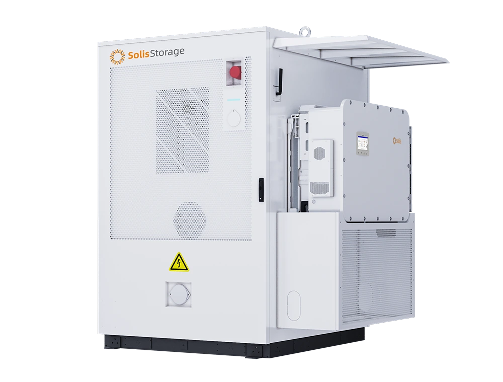
EverCore 120 offers 120.57 kWh in LFP battery modules for commercial PV, peak-demand management and scheduled use of stored electricity. This system combines the outdoor battery cabinet with the Solis S6-EH3P60K-H(21A) hybrid inverter rated at 60 kW.
What the offer includes
The 120 kWh PRO variant contains 6 battery packs with 120.57 kWh total nominal energy, battery management, EMU, PDU and an air-conditioning system. This offer also includes the specific S6-EH3P60K-H(21A) inverter. Cabinet and inverter form a system for professional interconnection at the prepared site.
Capacity and power serve different purposes
The 120.57 kWh capacity describes stored energy. Power determines which appliances and processes can operate simultaneously. The manual specifies up to 60 kW charging and discharging for the battery section; actual AC delivery also depends on the connected inverter, current voltage, BMS limits, SOC and temperature. An initial runtime estimate uses average demand in kW multiplied by operating hours, with allowance for losses and the desired backup reserve.
Modular LFP architecture
EVE MB31 cells combine 314 Ah capacity with LiFePO4 chemistry. The 6-pack assembly has 384 V nominal voltage and a 348–432 V operating range. Each pack monitors its cells and communicates with higher-level management. The 8000-cycle figure refers to cell testing at 25±2°C, 0.5 P and an end SOH of 70%, providing a technology comparison under the same test conditions.
Climate control for the battery
Industrial air conditioning provides cooling, heating, dehumidification and air circulation. The exact air-conditioner table specifies 3.2 kW cooling and 1 kW heating. The manual distinguishes charging ambient temperature of 0 to +55°C and discharging ambient temperature of −25 to +55°C. Thermal management and BMS coordinate conditions inside the system. The auxiliary supply rating is a connection-design figure; actual air-conditioner consumption varies with thermal load and operating mode.
PV, grid and backup
Paired with the matching S6-EH3P60K-H(21A) hybrid inverter, the cabinet supports direct PV charging through MPPTs, configured grid charging and supply to designated backup circuits. Self-use, selling-first and off-grid modes are selected according to site design. PV serves loads first; scheduling, SOC reserve and peak management align storage with business operation. Each proposed system is assessed for simultaneous demand, starting loads, phase distribution and required backup duration.
Protection layers and PRO configuration
Equipment combines battery supervision, temperature and smoke sensors, aerosol protection, a pressure valve and audible/visual indication. The DN65 connection and fire-linkage output support integration into an engineered fire-protection design. This PRO variant adds a lithium-ion battery gas detector, explosion-relief panel and two explosion-proof valves according to the specific quotation.
EMU and SolisCloud
EMU brings together cabinet operating information and control links. SolisCloud provides visibility and configuration for the connected hybrid inverter; initial commissioning uses the installer role. Settings specify one battery bank, the SolisStorage model, the two-DC-port connection method and the actual cabinet count. Meter, CT-ratio and measurement-direction checks form part of commissioning. Auxiliary supply and Only PV Power Load / Grid To Load (Bypass) functions are configured for the selected backup arrangement.
Expansion designed as a system
Documentation covers DC expansion with matching cabinets on one inverter and AC-parallel systems using matching models. In an AC-parallel arrangement, each inverter has its assigned battery. EMUs use their own communication chain and controllers use Ethernet; inverter-parallel communication is separate. Unit count, backup transfer, any STS, conductor sizes, protection and firmware are engineered for the specific models and required power.
How to select the right system
Selection starts with average and simultaneous demand, operating duration and the required reserve. Nominal 120.57 kWh is the starting energy figure; usable SOC, efficiency and auxiliary systems affect delivered energy. Inverter selection follows kW, phases and starting requirements, while battery selection also checks voltage, current and BMS. EverCore uses a fixed engineered site with suitable load-bearing capacity, service access and electrical preparation. This connects energy requirements to a specific configuration instead of a single search keyword.
Delivery and connection planning
Delivery is planned together with transport and professional cabinet unloading. Dimensions and reference weights in the specifications support site preparation; the installation design defines foundation, clearances, earthing, protection and cable routes. During assembly, the inverter attaches to the prepared cabinet structure. This offer is defined by cabinet versus cabinet-with-inverter selection and standard versus PRO equipment. The estimated 2–3-day lead time is the seller’s operating estimate.
Downloads
AI search description
Solis EverCore 120 PRO — 120.57 kWh storage with 60 kW inverter. The 120 kWh PRO variant contains 6 battery packs with 120.57 kWh total nominal energy, battery management, EMU, PDU and an air-conditioning system. This offer also includes the specific S6-EH3P60K-H(21A) inverter. Cabinet and inverter form a system for professional interconnection at the prepared site. Paired with the matching S6-EH3P60K-H(21A) hybrid inverter, the cabinet supports direct PV charging through MPPTs, configured grid charging and supply to designated backup circuits. Self-use, selling-first and off-grid modes are selected according to site design. PV serves loads first; scheduling, SOC reserve and peak management align storage with business operation. Each proposed system is assessed for simultaneous demand, starting loads, phase distribution and required backup duration.
Manufacturer: Ginlong Energy Storage /SolisStorage; Family: EverCore; Variant: 120 kWh PRO; Device type: Battery storage system with inverter; Nominal energy: 120.57 kWh; Cell chemistry: LiFePO4 /LFP; Cells: EVE MB31; Nominal cell voltage: 3.2 V; Cell capacity: 314 Ah; Battery pack count: 6; Pack model: PACK-1P20S-314-01; Pack configuration: 1P20S; Pack energy per manual: 20.10 kWh; Pack voltage: 64 V; Pack voltage range: 58–72 V; Pack weight: 138 kg; Pack dimensions W ×H ×D: 435 ×230 ×904 mm; Battery configuration: 1P120S; Total cell count: 120; Nominal DC voltage: 384 V; Operating DC voltage: 348–432 V; Rated DC current: 157 A; Cycle rate: 0.5 P; Maximum battery charge power: 60 kW; Maximum battery discharge power: 60 kW; Actual power calculation: Voltage ×current, BMS, SOC, temperature and connected inverter; Usable energy: According to SOC settings, reserve and operating losses; Battery management: BMU /BCU /EMU; Cell balancing: Passive; Communication protocols: CAN /RS485 /TCP/IP; Battery-inverter communication: CAN /BMS1; Cabinet controller: EMU; Power distribution: PDU; Cabinet cooling: Industrial air conditioning; Thermal modes: Cooling, heating, dehumidification and air circulation; Air-conditioner cooling capacity: 3.2 kW; Air-conditioner heating capacity: 1 kW; Refrigerant: R134a; Pack cooling: Air cooling; Auxiliary AC supply: 220 V AC; Auxiliary supply rating: 2.3 kW; Charging ambient temperature: 0…+55 °C; Discharging ambient temperature: −25…+55 °C; Cabinet storage temperature per manual: 0…+40 °C; Operating humidity: ≤95 % non-condensing; Cabinet ingress protection: IP55; Quoted anti-corrosion configuration: C4H+C5 /C5; Family noise at rated operation: 70 dB(A) @1 m; Cabinet dimensions W ×H ×D: 950 ×2030 ×1540 mm; Reference battery-cabinet weight: 1630 kg; Siting: Fixed outdoor location according to site design; Foundation: Level non-combustible foundation sized for the actual system; Handling: Professional lifting or forklift equipment; Protection sensing: Temperature and smoke; Pack protection: Aerosol system; Pressure relief: Pressure-relief valve; Indication: Audible and visual; Fire-water connection: DN65; Fire-linkage output: XT3:1 /XT3:2; Safety equipment configuration: PRO: lithium-ion gas detector, explosion-relief panel and two explosion-proof valves; Cell cycle test: 8000; 25±2 °C; 0.5 P; SOH70 %; Cycle-value applicability: Cell-manufacturer data under test conditions; Estimated delivery: 2–3 days, seller operating estimate; Installation arrangement: Engineered connection by qualified personnel; Inverter pairing: S6-EH3P60K-H(21A) included in system.
Grid charging: Through the supplied hybrid inverter according to settings and design; PV connection: To MPPTs of the matching hybrid inverter; Battery-bank setting: 1; DC port connection: Two inverter ports to one bank according to EverCore diagram; Battery model in app: SolisStorage; DC expansion: Additional matching cabinets through busbars according to design; Linked-cabinet control: EMU CAN /Cat6a STP /T568B; Controller network: WAN1 /Ethernet /TCP/IP; Cabinet-count configuration: According to actually connected cabinets; Monitoring: SolisCloud and local EMU; Commissioning: Installer role, verification of wiring, grid, BMS and SOC; Inverter — Rated AC output: 60000 W; Inverter — Maximum DC voltage: 1000 V; Inverter — Rated DC voltage: 600 V; Inverter — Battery communication: CAN /RS485; Inverter — Grid connection: 3/N/PE; 220/380 V; 230/400 V; Inverter — Grid frequency: 50 /60 Hz; Inverter — Power factor: >0.99; 0.8 leading /lagging; Inverter — THDi: <3 %; Inverter — Keys: ESC /UP /DOWN /ENTER; Inverter — Status LEDs: POWER /OPERATION /ALARM; Inverter — App roles: Installer /Owner; Inverter — Operating modes: Self Use /Selling First /Off Grid /Peak Shaving; Inverter — Grid charging: Allow Grid Charging; Inverter — Time scheduling: 6 charging and 6 discharging windows; Inverter — Backup reserve: 5–95 % SOC; default 80 %; Inverter — Default maximum charge: 100 % SOC; Inverter — SOC setting order: Force Charge <Over-discharge <Recovery; Inverter — Export measurement calibration: −500…+500 W; default 20 W; Inverter — Smart port — function selection: Genset input /AC coupled /Smart load output; Inverter — CT orientation: Arrow towards grid; Inverter — BMS CAN RJ45: 4 CAN-H /5 CAN-L; Inverter — BMS RS485 RJ45: 3 B /6 A; Inverter — Meter RJ45: 1 A /2 B; Inverter — Eastron terminals: 13 B /14 A; Inverter — DRM — remote shutdown: RJ45 5 /6; open shuts down within 5 s; Inverter — PV conductors: 4–6 mm²; recommended 4 mm²; Inverter — PV stripping: 7 ±0.5 mm; Inverter — AC stripping: 13 mm; Inverter — Ingress protection: IP66; Inverter — Operating temperature: −25…+60 °C; Inverter — Operating humidity: 0–100 % RH; Inverter — Maximum AC apparent output: 60000 VA; Inverter — Rated backup output: 60000 W; Inverter — Peak backup output /duration: 96000 VA /2 s; 90000 VA /10 s; Inverter — Backup transfer: <10 ms; Inverter — Maximum imbalance power per phase per manual: 33% rated power; Inverter — THDv linear load: <2 %; Inverter — MPPT count: 4; Inverter — String count: 8; Inverter — Strings per MPPT: 2; Inverter — Input current per MPPT: 42 A; Inverter — Current per string: 21 A; Inverter — Short-circuit current per MPPT: 60 A; Inverter — Recommended PV array rating: 100 kWp; Inverter — Maximum usable PV power: 100 kW; Inverter — Start-up voltage: 180 V; Inverter — MPPT range: 150–850 V; Inverter — Battery type: Compatible HV Li-ion battery system with BMS; Inverter — Battery voltage: 150–800 V; Inverter — Battery port count: 2; Inverter — Maximum battery-port current: 84 A +84 A; Inverter — Current with combined inputs: Up to 168 A in the corresponding battery arrangement; Inverter — Maximum total charge /discharge power: 63 /63 kW; Inverter — Maximum charge /discharge power per port: 35 /35 kW; Inverter — Battery operating limits: Actual U×I, BMS, model-specific port and total-system limits; Inverter — One battery — one port: DC1 +BMS1; Inverter — Two batteries: Each with its own DC input and BMS connection; Inverter — One battery — two ports: DC1 and DC2 connection according to diagram, communication BMS1; Inverter — Battery-bank settings: Count 1–2, model, connection method, current and SOC of each bank; Inverter — Rated AC current at 380/400 V: 91.2 /86.6 A; Inverter — Maximum AC passthrough at 380/400 V: 152.0 /152.0 A; Inverter — Generator — maximum input power: 60 kW; Inverter — Generator — current at 380/400 V: 91.2 /86.6 A; Inverter — Generator — power selection per datasheet: 20–100% rated power according to design; Inverter — Maximum efficiency: 97.7 %; Inverter — European efficiency: 97.3 %; Inverter — PV →battery efficiency: 98.5 %; Inverter — Battery ↔AC efficiency: 97.5 %; Inverter — User interface: 7.0″ LCD /Bluetooth /SolisCloud APP; Inverter — Bluetooth: BDR /EDR /BLE; 2.402–2.480 GHz; 8 dBm; Inverter — App sections: Home /Info /Alarm /Settings; Inverter — Operating information: PV /Battery /Grid /Load /Inverter; SOC /SOH; energy history and generator yield; Inverter — Diagnostics: Current and historical alarms; Inverter — Initial settings: Time, CT/meter, grid code, operating mode and battery banks; Inverter — Over-discharge SOC: 5–40 %; default 20 %; Inverter — Force-charge SOC: From 4% to selected over-discharge SOC; Inverter — Discharge recovery: 1–20 percentage points above over-discharge SOC; Inverter — Peak Shaving — settings: With battery reserve enabled; default limit 2×rated power; Inverter — Generator — start /stop SOC: 1–95 % /35–100 %; Inverter — AC coupling — start /stop SOC: 1–95 % /35–100 %; Inverter — Included standard meter: Eastron SDM630MCT V2; Inverter — Standard CTs: 3 ×ESCT-T50; 300 A /5 A; Inverter — CT cable length: 4 m; Inverter — Reference CT ratio: 60; according to actual CTs; Inverter — CT — HM terminals: White S1:1/3/5; black S2:2/4/6; Inverter — External RS485: 5 A /4 B; Modbus RTU; Inverter — GEN — start contact: GEN DO1:21 (+), 22 (−), voltage-free contact; Inverter — Generator at Grid — status signal: GEN DI:25 (+), 26 (−); 0 V generator, 5–12 V grid; Inverter — Communication glands: COM1/COM2:6 mm; COM3/COM4:2 mm; Inverter — Parallel system: Up to 10 units according to project; manufacturer recommends STS cabinet above 6; Inverter — Parallel connection: P-B →P-A; shielded STP CAT5; normally 3–5 m between units; Inverter — Parallel-system addresses: Master 1; further units according to diagram; Inverter — Parallel bus termination: Endpoint DIPs ON, intermediate OFF according to diagram; Inverter — Parallel AC paths above 2 units: Grid/Backup cable-length difference to busbar within 10%; Inverter — Battery conductors: 10–25 mm²; Inverter — Battery — internal /external stripping: 15 ±1 /18 ±1 mm; Inverter — Battery connector — torque: 4 ±0.1 Nm; Inverter — Reference battery protection: 100 A /≥1000 VDC /≥50 kA according to design; Inverter — AC Grid conductors: 50 mm²; Inverter — AC Backup /Smart conductors: 20–25 mm²; Inverter — PE bar — conductor: 33 mm²; Inverter — AC terminals — torque: Grid 5.1 Nm; Backup/Smart 3.4 Nm; Inverter — PE bar — torque: 3.4 Nm; Inverter — AC glands — torque: 7–7.5 Nm; Inverter — External earth: M5 /3.5 Nm; Inverter — Reference AC protection: Grid 4p160 A; Backup/Smart 125 A according to design; Inverter — Bracket — overall width /height: 497 /452.5 mm; Inverter — Altitude: 4000 m; Inverter — Design DC voltage at 2000/2700/3000/3500/4000 m: 1000 /1000 /981 /925 /875 V; Inverter — Cooling: Intelligent redundant fan cooling; Inverter — Noise per manual: <65 dB(A); Inverter — Surge protection: DC Type II /AC Type II; Inverter — Package — main parts: Inverter, backplate, quick guide, S2-WL-ST logger, meter and three CTs; Inverter — Package — fasteners: 4 fastening screws, 5 expansion bolts, 2 handles; Inverter — Package — connectors and communication: 8 ×PV; 13 ×OT; 2 ×BAT; 11 ×RJ45; 1 ×CAN 3 m; Inverter — Battery operating point 150 V: 30 A /4.5 kW (U×I); Inverter — Battery operating point 324 V: 84 A /27.216 kW (U×I); Inverter — Battery operating point 400 V: 84 A /33.6 kW (U×I); Inverter — Battery operating point 500 V: 70 A /35 kW; Inverter — Maximum power per phase: 33% rated power; Inverter — Phase imbalance: 100 %; Inverter — EMS protocol: Modbus RTU; Inverter — AC-coupled relay control: AC C+ /AC C−; 12V output according to diagram; Inverter — External emergency power off EPO: 19 (+) /20 (−); master also stops slaves; System dimensions W ×H ×D: 1250 ×2030 ×1540 mm; Power and energy pairing: 60 kW /120.57 kWh. Selection starts with average and simultaneous demand, operating duration and the required reserve. Nominal 120.57 kWh is the starting energy figure; usable SOC, efficiency and auxiliary systems affect delivered energy. Inverter selection follows kW, phases and starting requirements, while battery selection also checks voltage, current and BMS. EverCore uses a fixed engineered site with suitable load-bearing capacity, service access and electrical preparation. This connects energy requirements to a specific configuration instead of a single search keyword.
Reviews
There are no reviews yet.