





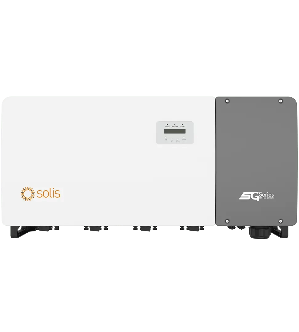
Description
Technical specifications
| Manufacturer | Solis / Ginlong Technologies |
|---|---|
| Model | Solis-100K-5G-PRO |
| Type and role | Three-phase grid-connected PV inverter |
| Offered configuration | DC switches, LCD and RS485 |
| Operating configuration | PV array and three-phase utility grid |
| Maximum DC voltage | 1100 V |
| Rated DC voltage | 600 V |
| Start-up voltage | 180 V |
| Grid conductors | 3 / N / PE |
| Rated grid voltage | 220 / 380 V; 230 / 400 V |
| Rated frequency | 50 / 60 Hz |
| Power factor | >0.99; adjustable 0.8 leading to 0.8 lagging |
| THDi | <3 % |
| Maximum efficiency | 98.5 % |
| Topology | Transformerless |
| DC connectors | MC4 |
| Inverter monitoring address | 01–99; default 01 |
| Controls | ESC / UP / DOWN / ENTER |
| LED indicators | POWER / OPERATION / ALARM |
| Displayed operating data | PV and phase voltages/currents, power, frequency, energy, status, serial number and version |
| Generation history | Daily, monthly and yearly energy |
| Alarm / warning history | Latest 100 records in each history |
| External EPM | 5G-EPM / Others-EPM according to actual device |
| Active and reactive power control | Power settings and PF Curve |
| DRM — logic interface | RJ45: pin 5 Switch_input1 / pin 6 Switch_input2 |
| DRM — response after opening | Limit to 0 W within 5 s when enabled according to grid profile |
| Service updates | HMI / DSP |
| String monitoring | Integrated |
| I/V curve scanning | Integrated function |
| I/V scan — start / step / points | 300–1000 V / 1–100 V / 60 |
| Grid check at start-up | 30–300 s |
| Service fan test | Fan Test |
| User-Def — grid-profile use | Service configuration with grid-operator permission; L–N ranges per manual |
| Ingress protection | IP66 |
| Relative operating humidity | 0–100 % RH |
| Maximum altitude | 4000 m |
| Storage temperature | −40 to +70 °C |
| Storage humidity | 0–95 % RH, non-condensing |
| Mounting position | Vertical or backward tilt up to 15° |
| Airflow clearance | 500 mm above, at the sides and above floor; 1000 mm in front as illustrated |
| Mounting structure | Firm fire-resistant wall with airflow |
| DC cable | 4–6 mm²; recommended 4 mm², PV1-F |
| DC — stripping length | 7 mm |
| Safety | IEC / EN 62109-1 / -2 |
| Estimated delivery | 2–3 days |
| Independent MPPT count | 8 |
| Maximum PV string count | 16 |
| Strings per MPPT | 2 |
| MPPT range | 160–1000 V |
| Input currents by MPPT | 40 A /32 A /40 A /32 A /40 A /32 A /40 A /32 A |
|---|---|
| Short-circuit current of each MPPT | 50 A |
| PV-input power groups | 4 |
| Power-group allocation | PV1–4; PV5–8; PV9–12; PV13–16 |
| Recommended group balance | Input-power difference up to 5% |
| String design | Module count, cold Voc, MPPT voltage, current and Isc |
| Panels on one MPPT | Matching type, rating, orientation, tilt and series count |
| Rated AC power | 100 kW |
| Maximum AC apparent power | 110 kVA |
| Rated current at 380/400 V | 152.0 /144.3 A |
| Maximum AC current | 167.1 A |
| European efficiency | 98.0 % |
| Night consumption | <2 W |
| LCD display | 2 ×20 |
| Communication | RS485 |
| Optional family communication | Wi-Fi /GPRS /PLC |
| Datalogger connector | COM1 /4-pin |
| Communication glands | COM2 RS485 IN /COM3 RS485 OUT |
| RS485 RJ45 pins | 1+4 A /2+5 B |
| RS485 terminal block | 1 A-IN /2 B-IN /3 A-OUT /4 B-OUT |
| RS485 cable | CAT5E STP /T568B |
| RS485 terminal conductors | 0.2–1.5 mm² |
| RS485 cable diameter | 5–10 mm |
| RS485 sheath /core stripping | 30 /8 mm |
| Export management | Through matching external EPM and metering according to design |
| AFCI | Integrated function, enabled in service settings |
| Detected-arc response | Shutdown and ARC-FAULT indication |
| Dimensions W ×H ×D | 1183 ×585 ×363 mm |
| Reference weight | 98 kg |
| Operating temperature | −30…+60 °C |
| Cooling | Intelligent redundant fan cooling |
| Packed-unit stacking | 4 |
| Mounting bracket — hole spacing | 1129 ×356 mm |
| Fastening screws | 2 ×M6×12 |
| Fastening torque | 2–3 Nm |
| External earthing | M10 /10–12 Nm |
| Earthing conductor | Cu, according to design and phase-conductor size |
| AC terminals | M10 OT /10–20 Nm |
| Maximum OT section per model table | 185 mm² |
| Recommended AC conductor in manual | 70 mm² |
| AC cable outer diameter | 38–56 mm /45 mm recommended |
| AC stripping | Sheath300 mm; cores OT crimp-area length +2–3 mm |
| DC tightening torque | 3–4 Nm |
| Reference AC protection | 200 A |
| Package contents | Inverter, bracket,2 M6×12 screws,DC connectors and manual |
| DC connector count | 16 |
| Storage in the project | Separately designed battery system with matching converter |
| EMC | IEC /EN 61000-6-2 /-4 |
| Model grid standards | G99 /IEC61727 /EN50549-1/2 /VDE4110 |
Generation for commercial PV
Solis-100K-5G-PRO converts PV-array energy into the three-phase grid of a business, production facility or larger building. Its 100 kW rating combines with 8 independent MPPTs for up to 16 strings. LCD and RS485 provide generation visibility and connection to suitable monitoring equipment. The offered configuration includes DC switches and is designed for a permanent grid-connected PV installation.
MPPTs matched to the actual wiring
8 MPPTs operate over 160–1000 V, with 600 V rated DC voltage and 180 V start-up. Tracker input-current ratings alternate 40 A and 32 A; the short-circuit limit is 50 A per MPPT. Each tracker has two string inputs. The design assigns specific modules to specific trackers according to current, voltage and array direction. The 1100 V maximum DC rating is also checked against open-circuit voltage at the lowest design temperature.
Balanced power groups
The internal layout comprises 4 power groups, each serving four PV inputs. The manufacturer recommends distributing power with no more than 5% difference between groups. Dedicated diagrams address uneven group loading with four 182 mm-module strings or three 210 mm-module strings. Such wiring is assessed as a whole using individual string power and the relevant trackers. The group allocation in the technical table supports larger-array design.
AC output and efficiency
The 100 kW rating describes delivery to a 220/380 V or 230/400 V three-phase connection at 50 or 60 Hz. Maximum apparent output is 110 kVA. Maximum efficiency reaches 98.5% and European efficiency 98.0%. Specified THDi is below 3%. Active/reactive power and power factor are configured within the grid-connection design; annual kWh generation follows module selection, irradiation, orientation and operating conditions.
LCD and generation history
Local LCD and suitable remote monitoring provide complementary views. The display shows power, status, PV/grid voltages and currents, frequency, and active/reactive/apparent values. History covers daily, monthly, yearly and total energy. Service information includes the last 100 alarms,100 warnings and firmware version. Buttons allow local navigation and screen locking.
RS485 links and monitoring
Standard RS485 supports daisy-chaining multiple inverters. RJ45 and terminal-block connections, addresses 01–99 with default 01 and separate COM2/COM3 pass-through interfaces are provided. COM1 serves a suitable optional datalogger. Wi-Fi, GPRS and PLC are selected as specific additional configurations. Cable, shielding and conductor order follow this family’s communication diagram.
Controlling the connected plant
External EPM with matching metering integrates the inverters into plant power management. The 5G-EPM or Others-EPM service selection matches the actual equipment, and commissioning verifies Fail Safe behavior. DRM uses pins 5 and 6; when enabled, a closed contact permits normal operation and an open contact limits output to zero within five seconds. Qualified personnel configure the grid profile and control parameters for the specific connection.
String diagnostics and AFCI
I/V-curve scanning uses a 300–1000 V starting point,1–100 V intervals and 60 data points. It supports service comparison of individual strings and their operating characteristics. Integrated AFCI is enabled in the designated service settings; a detected DC arc triggers shutdown and ARC-FAULT indication. Generation information, diagnostic history and wiring checks complement each other during plant maintenance.
Construction for permanent installations
The 1183 ×585 ×363 mm enclosure has a reference weight of 98 kg. IP66 provides dust-tight construction and protection against powerful water jets. The −30 to +60°C operating range combines with intelligent redundant fan cooling. Installation uses a fixed non-combustible wall or suitable frame, airflow and service access. Vertical mounting may use up to 15° rearward tilt according to the manual.
Power wiring and protection
DC connection uses 4–6 mm² copper PV conductors and matching MC4 connectors. AC terminals use crimped OT lugs, with 70 mm² recommended in the manual and conductor sizing determined by the actual design. The model table specifies a 185 mm² OT maximum. Reference AC overcurrent protection for the 100 kW model is 200 A. External protective earthing, conductor preparation and tightening torques follow the manual and design. Grid connection must comply with local requirements.
Part of a grid-connected energy system
The offer includes theSolis-100K-5G-PRO inverter, mounting bracket, two M6×12 fastening screws,16 DC connectors and manual. Panels, mounting structures, protection, metering and monitoring are selected for the plant design. Added storage uses a separately engineered battery system with matching converter and control. Power in kW and required stored energy in kWh are assessed separately so that the configuration matches demand patterns and the intended operation.
Downloads
AI search description
Solis-100K-5G-PRO — 100 kW three-phase grid inverter, 8 MPPTs. Solis-100K-5G-PRO converts PV-array energy into the three-phase grid of a business, production facility or larger building. Its 100 kW rating combines with 8 independent MPPTs for up to 16 strings. LCD and RS485 provide generation visibility and connection to suitable monitoring equipment. The offered configuration includes DC switches and is designed for a permanent grid-connected PV installation. The offer includes theSolis-100K-5G-PRO inverter, mounting bracket, two M6×12 fastening screws,16 DC connectors and manual. Panels, mounting structures, protection, metering and monitoring are selected for the plant design. Added storage uses a separately engineered battery system with matching converter and control. Power in kW and required stored energy in kWh are assessed separately so that the configuration matches demand patterns and the intended operation.
Manufacturer: Solis / Ginlong Technologies; Model: Solis-100K-5G-PRO; Type and role: Three-phase grid-connected PV inverter; Offered configuration: DC switches, LCD and RS485; Operating configuration: PV array and three-phase utility grid; Maximum DC voltage: 1100 V; Rated DC voltage: 600 V; Start-up voltage: 180 V; Grid conductors: 3 / N / PE; Rated grid voltage: 220 / 380 V; 230 / 400 V; Rated frequency: 50 / 60 Hz; Power factor: >0.99; adjustable 0.8 leading to 0.8 lagging; THDi: <3 %; Maximum efficiency: 98.5 %; Topology: Transformerless; DC connectors: MC4; Inverter monitoring address: 01–99; default 01; Controls: ESC / UP / DOWN / ENTER; LED indicators: POWER / OPERATION / ALARM; Displayed operating data: PV and phase voltages/currents, power, frequency, energy, status, serial number and version; Generation history: Daily, monthly and yearly energy; Alarm / warning history: Latest 100 records in each history; External EPM: 5G-EPM / Others-EPM according to actual device; Active and reactive power control: Power settings and PF Curve; DRM — logic interface: RJ45: pin 5 Switch_input1 / pin 6 Switch_input2; DRM — response after opening: Limit to 0 W within 5 s when enabled according to grid profile; Service updates: HMI / DSP; String monitoring: Integrated; I/V curve scanning: Integrated function; I/V scan — start / step / points: 300–1000 V / 1–100 V / 60; Grid check at start-up: 30–300 s; Service fan test: Fan Test; User-Def — grid-profile use: Service configuration with grid-operator permission; L–N ranges per manual; Ingress protection: IP66; Relative operating humidity: 0–100 % RH; Maximum altitude: 4000 m; Storage temperature: −40 to +70 °C; Storage humidity: 0–95 % RH, non-condensing; Mounting position: Vertical or backward tilt up to 15°; Airflow clearance: 500 mm above, at the sides and above floor; 1000 mm in front as illustrated; Mounting structure: Firm fire-resistant wall with airflow; DC cable: 4–6 mm²; recommended 4 mm², PV1-F; DC — stripping length: 7 mm; Safety: IEC / EN 62109-1 / -2; Estimated delivery: 2–3 days; Independent MPPT count: 8; Maximum PV string count: 16; Strings per MPPT: 2; MPPT range: 160–1000 V; Input currents by MPPT: 40 A /32 A /40 A /32 A /40 A /32 A /40 A /32 A; Short-circuit current of each MPPT: 50 A; PV-input power groups: 4; Power-group allocation: PV1–4; PV5–8; PV9–12; PV13–16; Recommended group balance: Input-power difference up to 5%; String design: Module count, cold Voc, MPPT voltage, current and Isc.
Panels on one MPPT: Matching type, rating, orientation, tilt and series count; Rated AC power: 100 kW; Maximum AC apparent power: 110 kVA; Rated current at 380/400 V: 152.0 /144.3 A; Maximum AC current: 167.1 A; European efficiency: 98.0 %; Night consumption: <2 W; LCD display: 2 ×20; Communication: RS485; Optional family communication: Wi-Fi /GPRS /PLC; Datalogger connector: COM1 /4-pin; Communication glands: COM2 RS485 IN /COM3 RS485 OUT; RS485 RJ45 pins: 1+4 A /2+5 B; RS485 terminal block: 1 A-IN /2 B-IN /3 A-OUT /4 B-OUT; RS485 cable: CAT5E STP /T568B; RS485 terminal conductors: 0.2–1.5 mm²; RS485 cable diameter: 5–10 mm; RS485 sheath /core stripping: 30 /8 mm; Export management: Through matching external EPM and metering according to design; AFCI: Integrated function, enabled in service settings; Detected-arc response: Shutdown and ARC-FAULT indication; Dimensions W ×H ×D: 1183 ×585 ×363 mm; Reference weight: 98 kg; Operating temperature: −30…+60 °C; Cooling: Intelligent redundant fan cooling; Packed-unit stacking: 4; Mounting bracket — hole spacing: 1129 ×356 mm; Fastening screws: 2 ×M6×12; Fastening torque: 2–3 Nm; External earthing: M10 /10–12 Nm; Earthing conductor: Cu, according to design and phase-conductor size; AC terminals: M10 OT /10–20 Nm; Maximum OT section per model table: 185 mm²; Recommended AC conductor in manual: 70 mm²; AC cable outer diameter: 38–56 mm /45 mm recommended; AC stripping: Sheath300 mm; cores OT crimp-area length +2–3 mm; DC tightening torque: 3–4 Nm; Reference AC protection: 200 A; Package contents: Inverter, bracket,2 M6×12 screws,DC connectors and manual; DC connector count: 16; Storage in the project: Separately designed battery system with matching converter; EMC: IEC /EN 61000-6-2 /-4; Model grid standards: G99 /IEC61727 /EN50549-1/2 /VDE4110.
Reviews
There are no reviews yet.