





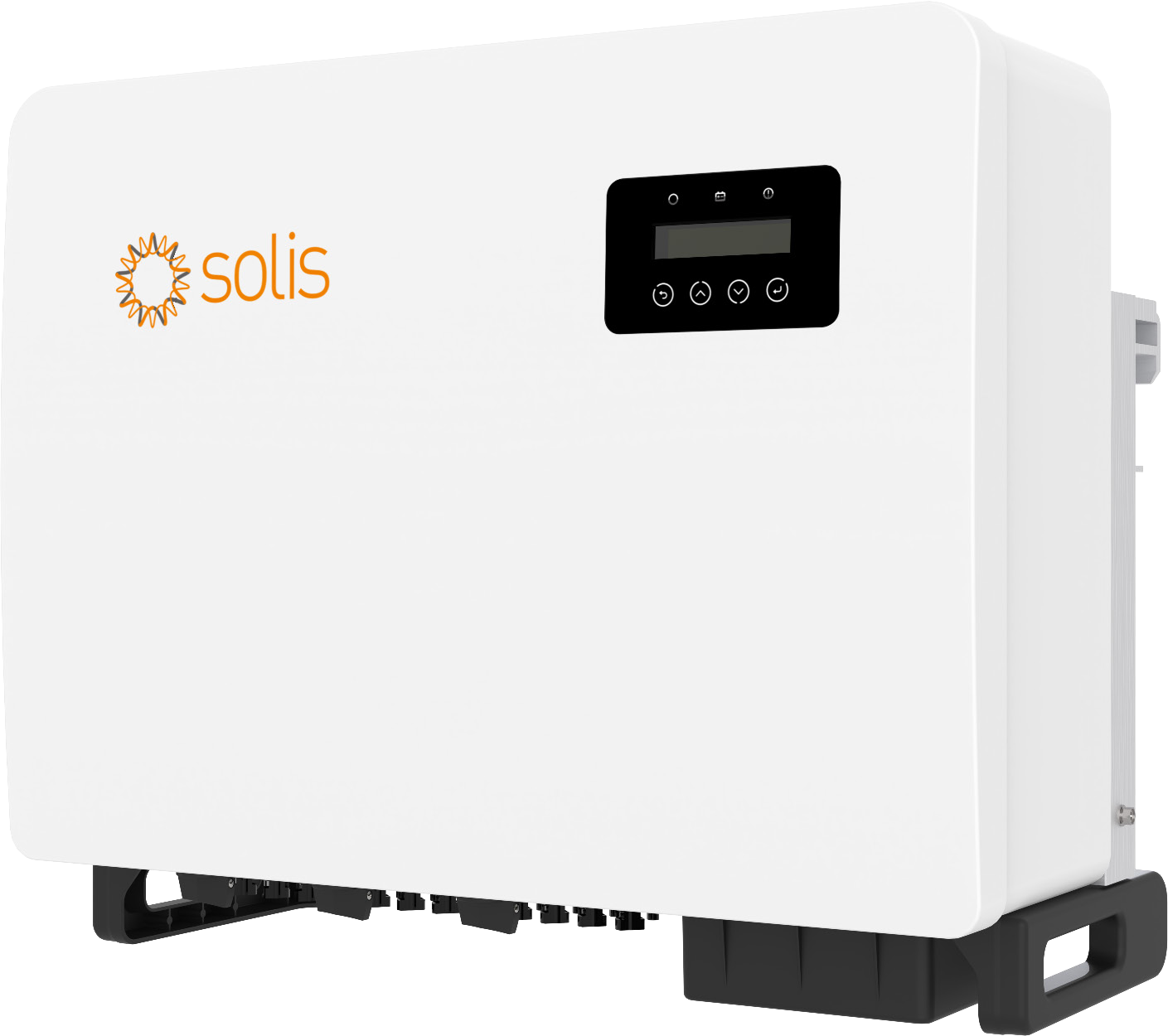
Description
Technical specifications
| Manufacturer | Solis / Ginlong Technologies |
|---|---|
| Model | S5-GC50K |
| Type and role | Three-phase grid-connected PV inverter |
| Offered configuration | Standard 400V model with 5 MPPTs and DC switch |
| Operating configuration | PV array and three-phase utility grid |
| Maximum DC voltage | 1100 V |
| Rated DC voltage | 600 V |
| Start-up voltage | 195 V |
| MPPT range | 180–1000 V |
| Full-load MPPT range | 550–850 V |
| Maximum input current per MPPT | 32 A / MPPT |
| Maximum short-circuit current per MPPT | 40 A / MPPT |
| Independent MPPT count | 5 |
| Maximum PV string count | 10 |
| Strings per MPPT | 2 / MPPT |
| Rated AC power | 50000 W |
| Maximum AC power | 55000 W |
| Maximum apparent AC power | 55000 VA |
| Grid conductors | 3 / N / PE |
| Rated grid voltage | 220 / 380 V; 230 / 400 V |
| Rated frequency | 50 / 60 Hz |
| Rated current at 380/400 V | 76.0 / 72.2 A |
| Maximum AC current | 83.6 A |
| Power factor | >0.99; adjustable 0.8 leading to 0.8 lagging |
| THDi | <3 % |
| Maximum efficiency | 98.7 % |
| European efficiency | 98.3 % |
| Topology | Transformerless |
| Night consumption | <1 W |
| DC polarity protection | Integrated function |
| Short-circuit protection | Integrated function |
| AC overcurrent protection | Integrated function |
| Surge protection | DC Type II / AC Type II |
| Grid monitoring | Integrated function |
| Anti-islanding protection | Integrated function |
| Temperature protection | Integrated function |
| Multi-peak MPPT scanning | Integrated function |
| DC switch | Integrated function |
| AFCI 2.0 arc protection | Optional configuration |
| DC connectors | MC4 |
| AC terminal connection | OT terminal block up to 70 mm²; L1 / L2 / L3 / N / PE |
| AC — phase / PE lugs | M8 / M6 |
| AC — neutral connection | With or without neutral according to local grid requirements |
| Communication | RS485 / USB |
| Communication connectors | 4-pin COM for data logger; 16-pin COM for RS485, meter and DRM |
| COM — nut / terminals | 3.5–4 Nm / 0.4–0.6 Nm |
| 16-pin COM — DRM pins 9–12 | 9 DRM1/5; 10 DRM2/6; 11 DRM3/7; 12 DRM4/8 |
| 16-pin COM — supply pins | 15 V+ 12 V; 16 V− GND |
| 16-pin COM — reserved pins | 5 / 8 |
| RS485 — IN / OUT terminals | 16pin COM: 3 A / 4 B IN; 6 A / 7 B OUT |
| RS485 — conductor / cable diameter | 0.75–3 mm² / 4–6 mm |
| COM — conductor stripping | 10–12 mm |
| Digital meter | Compatible Solis three-phase meter with external CTs according to design |
| Meter — communication terminals | Meter 21 A / 22 B → pins 1 A / 2 B of 16-pin COM |
| Remote monitoring | Optional Wi-Fi / GPRS / LAN loggers and Wi-Fi / GPRS box for multiple devices |
| Inverter monitoring address | 01–99; default 01 |
| LCD display | LCD with capacitive touch buttons |
| Controls | ESC / UP / DOWN / ENTER |
| LED indicators | POWER / OPERATION / ALARM |
| Displayed operating data | PV and phase voltages/currents, power, frequency, energy, status, serial number and version |
| Generation history | Daily, monthly and yearly energy |
| Alarm / warning history | Latest 100 records in each history |
| Export control | Internal EPM; Meter in Load / Meter in Grid / Consumption Monitor |
|---|---|
| Export-limit modes | 01 average / 02 according to lowest-loaded phase |
| 24-hour consumption monitoring | Grid-side meter, 24H Switch and Solis monitoring |
| Meter failsafe | Configurable alarm and generation stop on metering loss |
| External EPM | 5G-EPM / Others-EPM according to actual device |
| Active and reactive power control | Active/reactive output settings and grid working mode |
| DRM — logic interface | 16pin COM: 13 RefGen / 14 Com/DRM0 |
| DRM — response after opening | Limit to 0 W within 5 s when enabled according to grid profile |
| Service updates | HMI / DSP |
| Service compensation settings | Output energy and voltage calibration for grid-operator requirements |
| String monitoring | Integrated |
| PID recovery | Optional configuration |
| Night reactive-power compensation | Night SVG; configuration according to design |
| Night-function selection | Select PID-recovery or night reactive-power-compensation configuration according to design |
| I/V curve scanning | Integrated function |
| I/V scan — start / step / points | 100–1100 V / 1–100 V / 60 |
| Service fan test | Fan Test |
| User-Def — grid-profile use | Service configuration with grid-operator permission; L–N ranges per manual |
| User-Def — overvoltage OV-G-V1 / V2 | 220–374 V; 0.01–300 s |
| User-Def — undervoltage UN-G-V1 / V2 | 110–277 V; 0.01–300 s |
| User-Def — overfrequency OV-G-F1 / F2 | 50.1–65 Hz; 0.01–300 s |
| User-Def — underfrequency UN-G-F1 / F2 | 45–59.9 Hz; 0.01–300 s |
| User-Def — Startup-T / Restore-T | 10–600 s / 10–600 s |
| Dimensions W × H × D | 691 × 578 × 338 mm |
| Weight | 53.7 kg |
| Ingress protection | IP66 |
| Corrosion resistance | C5 |
| Operating temperature | −25 to +60 °C |
| Relative operating humidity | 0–100 % RH |
| Cooling | Intelligent fan cooling |
| Typical noise | <55 dB(A) |
| Maximum altitude | 4000 m |
| Storage temperature | −40 to +70 °C |
| Storage humidity | 0–95 % RH, non-condensing |
| Stacking packaged units | Maximum 4 units high |
| Mounting position | Vertical or backward tilt up to 15° |
| Airflow clearance | 500 mm at sides and above floor, 800 mm above enclosure and 1000 mm in front per figure3.1 |
| Mounting structure | Firm fire-resistant wall or metal rack with airflow |
| Mounting — anchors in manual | Wall M10 × 90, maximum hole depth 90 mm; rack M10 × 40 |
| Mounting — bracket dimensions | 636 × 272 mm; Ø11 mm; 44.5 / 24 / 11 mm |
| Mounting — bracket / fastening torque | 30–35 Nm / 2–3 Nm |
| Rack mounting — hole and torque | Ø12.5 mm / 35 Nm |
| Handling and lifting points | Two people, integrated handles and suitable lifting technique |
| External earthing | Copper 25–50 mm² per connection table, at least half the phase conductor size; external M10 lug, 5–6 Nm |
| DC cable | 4–6 mm²; recommended 4 mm², PV1-F; diameter 5.5–9 mm |
| DC — stripping length | 7 mm |
| DC — connector torque | 3–4 Nm |
| AC cable | Terminal range 10–70 mm²; connection overview 35–70 mm²; recommended 35 mm² |
| AC — cable outer diameter | 37–44 mm; recommended 40 mm |
| AC — sheath and conductor stripping | Sheath about 300 mm; conductor S2 = OT crimp length S1 + 2–3 mm |
| AC — terminal torque | 10–20 Nm |
| Recommended AC breaker | 100 A |
| Package — inverter / bracket | 1 / 1 |
| Package — cross / hex screws | 4 × M4 × 14 / 2 × M6 × 12 |
| Package — DC connectors | 10 |
| Package — AC cover / 16-pin COM / tool / manual | 1 / 1 / 1 / 1 |
| Optional system components | Compatible three-phase CT meter, logger and external EPM according to design |
| Safety | IEC / EN 62109-1 / -2 |
| EMC | IEC / EN 61000-6-1 / -2 / -3 / -4 |
| Grid standards | G99; VDE-AR-N 4105 / VDE V 0124; EN 50549-1; VDE 0126 / UTE C 15 / VFR:2019; RD 1699 / RD 244 / UNE 206006 / UNE 206007-1; CEI 0-21; C10/11; NRS 097-2-1; EIFS 2018.2; IEC 62116 / 61727 / 60068 / 61683; EN 50530 |
| Estimated delivery | 2–3 days |
Generation for business and industry
S5-GC50K converts module energy for the three-phase supply point of a commercial site, hall or industrial building. Its 50 kW rating describes instantaneous conversion; daily kWh depend on irradiation and array design. The operating system consists of PV modules, grid inverter and connected utility grid. Generation serves local consumption and grid export is managed for the actual connection.
Distributing arrays across MPPTs
5 independent trackers serve up to 10 strings, two per MPPT. Maximum input current is 32 A and short-circuit current 40 A per tracker. Start-up voltage is 195 V, MPPT range 180–1000 V and full-load range 550–850 V. Maximum DC voltage is 1100 V. Each MPPT group uses matching module type and count with corresponding orientation; design checks currents and open-circuit voltage at the local minimum temperature.
Output and efficient conversion
Rated output of 50000 W is complemented by maximum 55000 W and 55000 VA. The manufacturer specifies 83.6 A maximum AC current and 76.0 / 72.2 A rated current at 380/400 V. Connection 3/N/PE uses 220/380 or 230/400 V at 50/60 Hz. Maximum efficiency is 98.7 %, European efficiency 98.3 % and THDi below 3 %. Adjustable power factor supports grid requirements. Transformerless construction has night consumption below 1 W.
Metering for export and consumption
A compatible three-phase meter with external current transformers provides energy-flow data. Terminals 21 A and 22 B of the illustrated meter connect to pins 1 A and 2 B of the 16-pin COM. The manual shows grid-side and load-side metering for export control. A 24-hour overview uses a grid-side meter, enabled 24H Switch and Solis monitoring. Select the meter and transformers for the actual installation.
Output and export management
Internal EPM offers Meter in Load, Meter in Grid and Consumption Monitor. Mode 01 uses average three-phase consumption; mode 02 follows the lowest-loaded phase. Permitted export is configured for the connection design. Configurable failsafe can alarm and stop generation on metering loss. External control supports 5G-EPM or Others-EPM according to the device. Commissioning verifies metering direction and overall response.
Multi-device communication
The 4-pin COM accepts an optional logger for one inverter. The 16-pin COM combines RS485, metering and logic control. Daisy-chain communication uses pins 3/4 as input and 6/7 as output; addresses range 01–99, default 01. The manual lists Wi-Fi, GPRS and LAN loggers and Wi-Fi/GPRS boxes for multiple devices. Communication cable uses 0.75–3 mm² conductors, 4–6 mm diameter and 10–12 mm stripping; the full pinout appears in the technical overview and gallery.
Generation overview and I/V curves
The LCD with capacitive buttons shows MPPT and individual string voltages/currents, output, frequency, energy and operating state. Daily, monthly and yearly history and the latest 100 alarms and 100 warnings are available. Individual-string I/V scanning sets a 100–1100 V start and 1–100 V step with 60 data points. Service menus include fan testing, HMI/DSP updates and output-energy/voltage calibration for grid-operator requirements.
Durable construction and environment
The 691 × 578 × 338 mm enclosure weighs 53.7 kg. IP66 provides dust-tight protection against powerful water jets; C5 corrosion resistance complements suitable indoor or outdoor placement. Intelligent fan cooling supports −25 to +60 °C operation at 0–100 % humidity and altitude up to 4000 m. Typical noise is below 55 dB(A). The site provides airflow and shelter from direct sun. Storage conditions are −40 to +70 °C and 0–95 % non-condensing humidity; packaged units may be stacked up to four high.
Mounting and power terminals
Mount on a fire-resistant wall or metal rack vertically or tilted backward up to 15°. Exact bracket dimensions, clearances and torques appear in the technical overview. Two people and suitable technique use the integrated handles. AC terminals accept M8 lugs, PE uses M6 and the separate external earth point uses M10. Recommended AC conductor size is 35 mm² and this model’s breaker is 100 A. Neutral connection follows local grid requirements. DC uses MC4 and 4–6 mm² copper conductors.
Protection and night-function selection
Integrated protection covers DC polarity, short circuit, AC overcurrent, grid monitoring, anti-islanding and temperature; Type II surge protection is fitted on DC and AC sides. The current matrix listsAFCI 2.0 as optional. Night functions use a selected PID-recovery or Night SVG reactive-power-compensation configuration. The European logic interface uses pins 13 RefGen and 14 Com/DRM0; when enabled under the grid profile, opening the contact reduces output to 0 W within five seconds.
Equipment and matching components
The package includes the inverter, bracket, four M4 × 14 screws, two M6 × 12 screws, 10 DC connectors, AC terminal cover, 16-pin COM connector, unlocking tool and manual. The offer includes the DC switch. Modules, CT meter, logger, protection and mounting components are selected for the whole plant. Design compares kW output with consumption patterns and kWh energy. Any storage uses a separate compatible battery system and appropriate converter. Batterado helps match the components for the connection.
Downloads
- Solis S5-GC 50–60 kW — datasheet V3.8
- Solis S5-GC 50–60 kW — EUR user manual V1.3
- Complete product overview — Markdown
AI search description
High-output PV for commercial and industrial sites with flexible array grouping. Solis S5-GC50K delivers 50 kW rated output to a three-phase grid and connects up to 10 strings through 5 independent MPPTs. Each tracker supports 32 A and a 180–1000 V operating range. Up to 98.7 % efficiency, intelligent fan cooling, IP66 and C5 corrosion resistance support demanding installations at suitable locations. String monitoring and I/V scanning provide insight into generation. A compatible meter adds export control and suitable Solis monitoring enables a 24-hour consumption view. The practical 16-pin COM combines metering, multi-inverter communication and logic control. This offer includes the DC switch and standard connection components. S5-GC50K converts module energy for the three-phase supply point of a commercial site, hall or industrial building. Its 50 kW rating describes instantaneous conversion; daily kWh depend on irradiation and array design. The operating system consists of PV modules, grid inverter and connected utility grid. Generation serves local consumption and grid export is managed for the actual connection. The package includes the inverter, bracket, four M4 × 14 screws, two M6 × 12 screws, 10 DC connectors, AC terminal cover, 16-pin COM connector, unlocking tool and manual. The offer includes the DC switch. Modules, CT meter, logger, protection and mounting components are selected for the whole plant. Design compares kW output with consumption patterns and kWh energy. Any storage uses a separate compatible battery system and appropriate converter. Batterado helps match the components for the connection.
Manufacturer: Solis / Ginlong Technologies; Model: S5-GC50K; Type and role: Three-phase grid-connected PV inverter; Offered configuration: Standard 400V model with 5 MPPTs and DC switch; Operating configuration: PV array and three-phase utility grid; Maximum DC voltage: 1100 V; Rated DC voltage: 600 V; Start-up voltage: 195 V; MPPT range: 180–1000 V; Full-load MPPT range: 550–850 V; Maximum input current per MPPT: 32 A / MPPT; Maximum short-circuit current per MPPT: 40 A / MPPT; Independent MPPT count: 5; Maximum PV string count: 10; Strings per MPPT: 2 / MPPT; Rated AC power: 50000 W; Maximum AC power: 55000 W; Maximum apparent AC power: 55000 VA; Grid conductors: 3 / N / PE; Rated grid voltage: 220 / 380 V; 230 / 400 V; Rated frequency: 50 / 60 Hz; Rated current at 380/400 V: 76.0 / 72.2 A; Maximum AC current: 83.6 A; Power factor: >0.99; adjustable 0.8 leading to 0.8 lagging; THDi: <3 %; Maximum efficiency: 98.7 %; European efficiency: 98.3 %; Topology: Transformerless; Night consumption: <1 W; DC polarity protection: Integrated function; Short-circuit protection: Integrated function; AC overcurrent protection: Integrated function; Surge protection: DC Type II / AC Type II; Grid monitoring: Integrated function; Anti-islanding protection: Integrated function; Temperature protection: Integrated function; Multi-peak MPPT scanning: Integrated function; DC switch: Integrated function; AFCI 2.0 arc protection: Optional configuration; DC connectors: MC4; AC terminal connection: OT terminal block up to 70 mm²; L1 / L2 / L3 / N / PE; AC — phase / PE lugs: M8 / M6; AC — neutral connection: With or without neutral according to local grid requirements; Communication: RS485 / USB; Communication connectors: 4-pin COM for data logger; 16-pin COM for RS485, meter and DRM; COM — nut / terminals: 3.5–4 Nm / 0.4–0.6 Nm; 16-pin COM — DRM pins 9–12: 9 DRM1/5; 10 DRM2/6; 11 DRM3/7; 12 DRM4/8; 16-pin COM — supply pins: 15 V+ 12 V; 16 V− GND; 16-pin COM — reserved pins: 5 / 8; RS485 — IN / OUT terminals: 16pin COM: 3 A / 4 B IN; 6 A / 7 B OUT; RS485 — conductor / cable diameter: 0.75–3 mm² / 4–6 mm; COM — conductor stripping: 10–12 mm; Digital meter: Compatible Solis three-phase meter with external CTs according to design; Meter — communication terminals: Meter 21 A / 22 B → pins 1 A / 2 B of 16-pin COM; Remote monitoring: Optional Wi-Fi / GPRS / LAN loggers and Wi-Fi / GPRS box for multiple devices; Inverter monitoring address: 01–99; default 01; LCD display: LCD with capacitive touch buttons; Controls: ESC / UP / DOWN / ENTER; LED indicators: POWER / OPERATION / ALARM; Displayed operating data: PV and phase voltages/currents, power, frequency, energy, status, serial number and version.
Generation history: Daily, monthly and yearly energy; Alarm / warning history: Latest 100 records in each history; Export control: Internal EPM; Meter in Load / Meter in Grid / Consumption Monitor; Export-limit modes: 01 average / 02 according to lowest-loaded phase; 24-hour consumption monitoring: Grid-side meter, 24H Switch and Solis monitoring; Meter failsafe: Configurable alarm and generation stop on metering loss; External EPM: 5G-EPM / Others-EPM according to actual device; Active and reactive power control: Active/reactive output settings and grid working mode; DRM — logic interface: 16pin COM: 13 RefGen / 14 Com/DRM0; DRM — response after opening: Limit to 0 W within 5 s when enabled according to grid profile; Service updates: HMI / DSP; Service compensation settings: Output energy and voltage calibration for grid-operator requirements; String monitoring: Integrated; PID recovery: Optional configuration; Night reactive-power compensation: Night SVG; configuration according to design; Night-function selection: Select PID-recovery or night reactive-power-compensation configuration according to design; I/V curve scanning: Integrated function; I/V scan — start / step / points: 100–1100 V / 1–100 V / 60; Service fan test: Fan Test; User-Def — grid-profile use: Service configuration with grid-operator permission; L–N ranges per manual; User-Def — overvoltage OV-G-V1 / V2: 220–374 V; 0.01–300 s; User-Def — undervoltage UN-G-V1 / V2: 110–277 V; 0.01–300 s; User-Def — overfrequency OV-G-F1 / F2: 50.1–65 Hz; 0.01–300 s; User-Def — underfrequency UN-G-F1 / F2: 45–59.9 Hz; 0.01–300 s; User-Def — Startup-T / Restore-T: 10–600 s / 10–600 s; Dimensions W × H × D: 691 × 578 × 338 mm; Weight: 53.7 kg; Ingress protection: IP66; Corrosion resistance: C5; Operating temperature: −25 to +60 °C; Relative operating humidity: 0–100 % RH; Cooling: Intelligent fan cooling; Typical noise: <55 dB(A); Maximum altitude: 4000 m; Storage temperature: −40 to +70 °C; Storage humidity: 0–95 % RH, non-condensing; Stacking packaged units: Maximum 4 units high; Mounting position: Vertical or backward tilt up to 15°; Airflow clearance: 500 mm at sides and above floor, 800 mm above enclosure and 1000 mm in front per figure3.1; Mounting structure: Firm fire-resistant wall or metal rack with airflow; Mounting — anchors in manual: Wall M10 × 90, maximum hole depth 90 mm; rack M10 × 40; Mounting — bracket dimensions: 636 × 272 mm; Ø11 mm; 44.5 / 24 / 11 mm; Mounting — bracket / fastening torque: 30–35 Nm / 2–3 Nm; Rack mounting — hole and torque: Ø12.5 mm / 35 Nm; Handling and lifting points: Two people, integrated handles and suitable lifting technique; External earthing: Copper 25–50 mm² per connection table, at least half the phase conductor size; external M10 lug, 5–6 Nm; DC cable: 4–6 mm²; recommended 4 mm², PV1-F; diameter 5.5–9 mm; DC — stripping length: 7 mm; DC — connector torque: 3–4 Nm; AC cable: Terminal range 10–70 mm²; connection overview 35–70 mm²; recommended 35 mm²; AC — cable outer diameter: 37–44 mm; recommended 40 mm; AC — sheath and conductor stripping: Sheath about 300 mm; conductor S2 = OT crimp length S1 + 2–3 mm; AC — terminal torque: 10–20 Nm; Recommended AC breaker: 100 A; Package — inverter / bracket: 1 / 1; Package — cross / hex screws: 4 × M4 × 14 / 2 × M6 × 12; Package — DC connectors: 10; Package — AC cover / 16-pin COM / tool / manual: 1 / 1 / 1 / 1; Optional system components: Compatible three-phase CT meter, logger and external EPM according to design; Safety: IEC / EN 62109-1 / -2; EMC: IEC / EN 61000-6-1 / -2 / -3 / -4; Grid standards: G99; VDE-AR-N 4105 / VDE V 0124; EN 50549-1; VDE 0126 / UTE C 15 / VFR:2019; RD 1699 / RD 244 / UNE 206006 / UNE 206007-1; CEI 0-21; C10/11; NRS 097-2-1; EIFS 2018.2; IEC 62116 / 61727 / 60068 / 61683; EN 50530; Estimated delivery: 2–3 days.
Reviews
There are no reviews yet.