





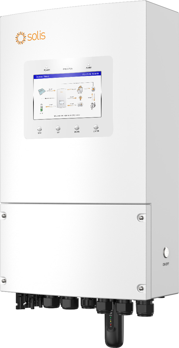
Description
Technical specifications
| Model | S6-EH1P9K-L-PLUS(21A) |
|---|---|
| Type and role | Single-phase hybrid inverter/charger for an external battery |
| PV — recommended maximum array | 18 kWp |
| PV — maximum usable input | 14.4 kW |
| PV — maximum input voltage | 500 V |
| PV — rated voltage | 330 V |
| PV — start-up voltage | 90 V |
| PV — MPPT voltage range | 90–435 V |
| PV — MPPT 1 / 2 current | 42 / 42 A |
| PV — current per DC input | 21 A |
| PV — MPPT 1 / 2 short-circuit current | 48 / 48 A |
| PV — MPPTs / total strings | 2 / 4 |
| Battery — type | Li-ion / lead-acid according to settings |
| Battery — voltage range / class | 40–60 V / 48 V |
| Battery — maximum charge / discharge current | 200 A / 200 A |
| Battery — power / BMS ports | 1 / 1 |
| Battery — charge / discharge power in manual | 9 kW |
| Battery — communication interfaces | CAN / RS485 |
| Battery — matching | Supported actual model, BMS profile and firmware; matching voltage and current |
| BMS — CAN RJ45 pins | 4 CAN-H / 5 CAN-L; EIA/TIA568B |
| BMS — Lithium Battery LV application profile | For a battery on the current matching list that is absent from the local model menu |
| Grid AC — rated output | 9 kW |
| Grid AC — maximum apparent power | 9 kVA |
| Grid AC — voltage and conductors | L/N/PE; 220 / 230 V |
| Grid AC — frequency | 50 / 60 Hz |
| Grid AC — current at 220 / 230 V | 40.9 / 39.1 A |
| Grid AC — power factor and range | >0.99; 0.8 leading to 0.8 lagging |
| Grid AC — THDi | <3 % |
| Grid input — voltage range | 187–253 V |
| Grid input — maximum current | 60 A |
| Backup — rated output | 9 kW |
| Backup — peak / duration | 18 kVA / 10 s |
| Backup — single-unit transfer | <10 ms |
| Backup — parallel transfer up to 6 units | <20 ms |
| Backup — voltage and conductors | L/N/PE; 220 / 230 V |
| Backup — frequency | 50 / 60 Hz |
| Backup — rated current at 220 / 230 V | 40.9 / 39.1 A |
| Backup — maximum AC passthrough | 60 A |
| Backup — THDv at linear load | <2 % |
| Generator — maximum input power | 9 kW |
| Generator — current at 220 / 230 V | 40.9 / 39.1 A |
| Generator — voltage and conductors | L/N/PE; 220 / 230 V |
| Generator — frequency | 50 / 60 Hz |
| Maximum efficiency | 96.2 % |
| EU efficiency | 96.1 % |
| PV → battery efficiency | 95.3 % |
| AC → battery efficiency | 93.9 % |
| Battery → AC efficiency | 93.8 % |
| Protection — surge protection | Yes |
| Protection — output overcurrent | Yes |
| Protection — insulation resistance | Yes |
| Protection — residual current | Yes |
| Protection — PV switch | Yes |
| Protection — PV reverse polarity | Yes |
| Protection — anti-islanding | Yes |
| Protection — offered AFCI | AFCI 1.0 — included in this configuration |
| Protection class / overvoltage category | I / II (PV,BAT); III (MAINS,BACKUP,GEN) |
| PV / battery topology | Non-isolated PV; isolated battery |
| Dimensions W × H × D | 335 × 560 × 253 mm |
| Weight | 23.8 kg |
| Ingress protection | IP66 |
|---|---|
| Operating temperature | −25 to +60 °C |
| Relative humidity | 0–100 % |
| Maximum altitude | 3000 m |
| Self-consumption | <40 W |
| Typical noise | <65 dB(A) |
| Cooling | Intelligent redundant fans |
| Control | 7.0 inch LCD; Bluetooth + APP |
| Physical PV / battery / AC connections | MC4 / Terminal Block / Terminal Block |
| Remote monitoring | SolisCloud with a suitable WiFi/LAN or 4G datalogger |
| Meter port | RJ45; 1 RS485-A / 2 RS485-B |
| Supported meter in manual | Eastron SDM120CTM; 9 RS485-B / 10 RS485-A |
| External control — protocol | Modbus RTU / RS485 |
| External RS485 — RJ45 pins | 5 RS485-A / 4 RS485-B |
| Parallel communication | P-A / P-B; CAN; CAT5 shielded; RJ45 |
| Parallel units | Up to 6 units in a configured system |
| Parallel DIP termination | Single unit: both down. Parallel: both DIP switches on at the first AND last inverter |
| Current transformer — terminals | CT 1 / 2 |
| Generator start at GEN — terminals | G-V 3 / 4 |
| Grid-side generator — detection input | GEN-DI 7 / 8 |
| Heat pump — control | SG-A 9 / 10 |
| Other interfaces | DRM; DI; DO ×2; USB logger |
| Bluetooth — band / power | BDR/EDR/BLE; 2.402–2.480 GHz; 8 dBm |
| Operating modes | Self-Use / Selling First / Off-Grid; TOU |
| Battery reserve — range / default | 20–100 % / 80 % |
| Smart Port — options | Generator / AC coupling / smart load according to configuration |
| AC coupling — power control | Frequency-Watt |
| Battery cable / lug in manual | 1/0 AWG / R60-8 |
| Battery fuse | 70 V / 300 A |
| Protective earthing | M4; 2 N·m; ≥4 mm² |
| AC tightening torque | 4–5 N·m |
| Mounting — orientation | Vertical on a suitable wall; tilt up to 5° |
| Grid standards | NRS097-2-1; IEC62116; IEC61727; IEC60068; IEC61683; EN50530; EN50549-1; MEA; PEA; NBR16149; NBR16150; G98; G99; CEI0-21; NTS631 TypeA |
| Safety / EMC | IEC/EN62109-1/-2; EN61000-6-2/-3 |
| PV — full-load MPPT range | 176–435 V |
| PV — maximum backfeed to array | 0 A |
| AC — inrush current / duration | 217 A / 10 µs |
| AC — maximum output fault current | 132 A |
| AC — grid frequency range | 45–55 / 55–65 Hz |
| AC — maximum input current at 220 / 230 V in manual | 60 A |
| Pollution degree | 3 |
| Mounting — clearance to other equipment | ≥150 mm |
| Mounting — lower edge above floor | ≥800 mm |
| Mounting — lower clearance by heat-source condition | ≥800 mm above a heat source, otherwise ≥500 mm |
| Mounting — supporting structure capacity | At least four times inverter weight |
| PV modules — class | IEC61730 Class A |
| Installation type | Permanent professional electrical installation with separate backup branch |
| Packaging in manual — core components | Inverter1×, backplate1×, fastening screw2×, expansion bolt4×, RJ45 4×, parallel cable1×, CT1×, quick guide1× |
| Packaging in manual — DC connectors | 4 × |
| Offered configuration | 9 kW,21 A inputs,single-phase meter configuration,AFCI 1.0 |
| GEN-DI — detection voltage | 5–12 V DC |
| Current transformer — standard in manual | ESCT-TA16-100A/50mA; 2000:1 |
| Parallel metering from 3 units | CTSA035-350A/50mA |
| Battery DC breaker recommended in manual | 300 A |
| AC breaker recommended in manual | 80 A |
| External RCD under local requirements | Type A, rated residual operating current ≥100 mA |
| Grid AC cable — recommended range | 8–4 AWG; C10-12 |
| Backup / GEN cable — recommended range | 10–4 AWG; C6-12 |
| Inrush current / duration | 217 A / 10 µs |
| Export calibration — range / default | −500 to +500 W / 20 W |
Energy sized around actual demand
The S6-EH1P9K-L-PLUS(21A) connects PV modules, an external low-voltage battery and a single-phase 220/230 V installation. Its 9 kW rating describes power for appliances, while the selected battery determines stored energy and runtime. Simultaneous demand, starting peaks and daily consumption are therefore considered separately. A designed system can serve a home, workshop, suitably wired holiday property or small business. The inverter is connected to an engineered electrical installation with suitable protection and locally applicable grid settings. Battery capacity and the load pattern then determine the practical operating window.
Two MPPTs for a well-designed array
The recommended maximum PV array is 18 kWp and maximum usable PV input is 14.4 kW. Two independent MPPT trackers allow suitable branches, for example for different roof orientations. The MPPT window is 90–435 V, start-up voltage 90 V and maximum input voltage 500 V. This model accepts 4 strings in total, with tracker current limits of 42/42 A. String design checks the actual modules, their cold-weather voltage and current. The same electrical principles apply to panels on a roof or a properly designed solar carport. Recommended array size and usable input power retain their distinct meanings.
48 V storage and correct battery matching
The 40–60 V input supports 48 V-class storage. This model permits up to 200 A charging and discharging through one battery power port with one BMS port. A lithium system uses an actual supported battery model, matching firmware and the correct application profile. The inverter CAN connection uses pin 4 for CAN-H and pin 5 for CAN-L. Available battery power also depends on voltage, permitted current and BMS control. Lead-acid systems use the corresponding settings and temperature sensor described in the manual. This allows storage to be selected around both required energy and power.
Fast backup and starting-load support
The backup output delivers 9 kW rated power. Off-grid operation supports brief starting loads with 18 kVA for 10 seconds. A single inverter changes from grid-connected to off-grid operation in under 10 ms; a parallel system of up to six units in under 20 ms. These specifications apply to a correctly designed backup branch with an adequate energy source. Motor starting requirements and sustained daily consumption are assessed individually. Maximum AC passthrough for this variant is 60 A. That rating describes a different electrical path from the DC battery charging current.
Grid charging and an operating schedule
The battery can charge from PV or an AC source. Maximum grid input current for this model is 60 A. Self-Use, Selling First and Off-Grid modes, together with TOU scheduling, coordinate generation, demand and storage. Schedules can reflect the building’s operating hours or different electricity tariffs. Configurable battery backup reserve ranges from 20 to 100%, with an 80% default. Practical runtime follows the selected battery capacity and appliance consumption. Commissioning sets suitable currents and operating behaviour for the complete system, allowing the charging plan to match the actual installation.
Generator, AC coupling and smart loads
This variant supports up to 9 kW generator input. Depending on settings, the Smart Port serves a generator, AC-coupled PV inverter or controlled load. AC coupling uses Frequency-Watt power control. Separate signals support further integration: GEN-V terminals 3/4 for generator starting, GEN-DI terminals 7/8 for grid/off-grid status detection with a grid-side generator and SG-A terminals 9/10 for a heat pump. Their functions are selected through the corresponding operating configuration. This provides defined interfaces for coordinating additional sources and appliances in a carefully designed energy system.
Metering, local visibility and external control
The display and Bluetooth app provide local access to operating information. SolisCloud enables remote monitoring with a suitable WiFi/LAN or 4G datalogger selected for the installation. The RS485 meter interface supports the Eastron SDM120CTM described in the manual. Meter-port pins 1/2 carry RS485-A/B, while the separate external-control port uses pins 5/4. That control port supports Modbus RTU for a connected supervisory controller. Distinguishing physical ports, their purpose and the actual protocol supports correct integration of metering, storage and system control.
Construction and system expansion
IP66 construction provides dust-tight protection and resistance to powerful water jets. The inverter operating range is −25 to +60 °C, dimensions are 335 × 560 × 253 mm and weight is 23.8 kg. The selected battery has its own environmental specifications. Up to six inverters can form a configured parallel system using P-A/P-B and shielded CAT5. This range’s manual specifies DIP termination separately for single and parallel operation. Expansion includes appropriately sized storage, metering and electrical protection. The datasheet, manual and complete product Markdown are hosted directly by Batterado for convenient reference.
Equipment that supports everyday operation
The two MPPT branches have defined current limits. The battery section provides up to 200 A and a galvanically isolated battery conversion path. The backup output adds brief overload support for starting loads. Self-Use and TOU coordinate solar self-consumption and charging. Smart Port integrates a suitably selected additional source or controlled load. LCD and Bluetooth provide local control, while the separate RS485 control port makes Modbus RTU available to a supervisory system. Each function has a distinct role in the overall energy design, providing concrete interfaces for a coordinated installation.
A permanent installation with defined connections
The inverter is designed for permanent professional electrical installation. Grid input, separate backup branch, battery and PV strings have defined connection points and suitable protection. The supporting structure is specified for at least four times the inverter weight; the manual requires at least 150 mm clearance to surrounding equipment and the lower edge at least 800 mm above the floor. An accessible display and free airflow support operation and maintenance. Dimensions, earthing, recommended battery wiring and communication pin assignments appear together in the technical overview.
Components of the complete energy system
The system combines this separate inverter, a supported battery, a designed PV array and metering appropriate to the selected topology. Power in kW follows simultaneous appliance demand; energy in kWh follows average consumption and operating time. Motor starting is considered separately. Mounting components described in the manual, including the backplate and CT, support installation. Remote access uses an appropriate datalogger, while supervisory control uses the actual supported protocol. Clear component roles make it possible to develop the installation further as the building’s energy requirements evolve.
Downloads
- Solis EH1P PLUS datasheet — V4.1
- Solis EH1P PLUS 21A manual — September 2025
- Complete product overview — Markdown
AI search description
Solar self-consumption, grid battery charging and fast backup for a single-phase installation. The Solis S6-EH1P9K-L-PLUS(21A) delivers 9 kW, works with an external 40–60 V battery and supports charging and discharging up to 200 A. Two MPPTs use up to 14.4 kW of PV power with a recommended array up to 18 kWp. A single unit changes to backup in under 10 ms and supports short starting loads with 18 kVA for 10 seconds. IP66 construction, a display and Bluetooth support integration into a home, workshop or business. The selected battery determines energy capacity in kWh; system power and runtime are sized around actual simultaneous loads. This is a separate inverter for a designed installation with suitable storage, panels and metering. The offered configuration includes single-phase metering. AFCI 1.0 is included in this offer.
Model: S6-EH1P9K-L-PLUS(21A); Type and role: Single-phase hybrid inverter/charger for an external battery; PV — recommended maximum array: 18 kWp; PV — maximum usable input: 14.4 kW; PV — maximum input voltage: 500 V; PV — rated voltage: 330 V; PV — start-up voltage: 90 V; PV — MPPT voltage range: 90–435 V; PV — MPPT 1 / 2 current: 42 / 42 A; PV — current per DC input: 21 A; PV — MPPT 1 / 2 short-circuit current: 48 / 48 A; PV — MPPTs / total strings: 2 / 4; Battery — type: Li-ion / lead-acid according to settings; Battery — voltage range / class: 40–60 V / 48 V; Battery — maximum charge / discharge current: 200 A / 200 A; Battery — power / BMS ports: 1 / 1; Battery — charge / discharge power in manual: 9 kW; Battery — communication interfaces: CAN / RS485; Battery — matching: Supported actual model, BMS profile and firmware; matching voltage and current; BMS — CAN RJ45 pins: 4 CAN-H / 5 CAN-L; EIA/TIA568B; BMS — Lithium Battery LV application profile: For a battery on the current matching list that is absent from the local model menu; Grid AC — rated output: 9 kW; Grid AC — maximum apparent power: 9 kVA; Grid AC — voltage and conductors: L/N/PE; 220 / 230 V; Grid AC — frequency: 50 / 60 Hz; Grid AC — current at 220 / 230 V: 40.9 / 39.1 A; Grid AC — power factor and range: >0.99; 0.8 leading to 0.8 lagging; Grid AC — THDi: <3 %; Grid input — voltage range: 187–253 V; Grid input — maximum current: 60 A; Backup — rated output: 9 kW; Backup — peak / duration: 18 kVA / 10 s; Backup — single-unit transfer: <10 ms; Backup — parallel transfer up to 6 units: <20 ms; Backup — voltage and conductors: L/N/PE; 220 / 230 V; Backup — frequency: 50 / 60 Hz; Backup — rated current at 220 / 230 V: 40.9 / 39.1 A; Backup — maximum AC passthrough: 60 A; Backup — THDv at linear load: <2 %; Generator — maximum input power: 9 kW; Generator — current at 220 / 230 V: 40.9 / 39.1 A; Generator — voltage and conductors: L/N/PE; 220 / 230 V; Generator — frequency: 50 / 60 Hz.
Battery — power / BMS ports: 1 / 1; BMS — CAN RJ45 pins: 4 CAN-H / 5 CAN-L; EIA/TIA568B; BMS — Lithium Battery LV application profile: For a battery on the current matching list that is absent from the local model menu; Operating temperature: −25 to +60 °C; External RS485 — RJ45 pins: 5 RS485-A / 4 RS485-B; Parallel communication: P-A / P-B; CAN; CAT5 shielded; RJ45; Parallel units: Up to 6 units in a configured system; Parallel DIP termination: Single unit: both down. Parallel: both DIP switches on at the first AND last inverter; Generator start at GEN — terminals: G-V 3 / 4; GEN-DI — detection voltage: 5–12 V DC; Parallel metering from 3 units: CTSA035-350A/50mA; Backup / GEN cable — recommended range: 10–4 AWG; C6-12.
Reviews
There are no reviews yet.